This thread has been locked.

If you have a related question, please click the "Ask a related question" button in the top right corner. The newly created question will be automatically linked to this question.

AWR6843: Questions on FCC certification

Part Number: AWR6843
Other Parts Discussed in Thread: IWR6843, , IWRL6843

Tool/software:

Hello team,

Customer referred below E2E post and asked me few questions. Can I ask your help on below?

AWR6843ISK: AWR6843ISK / IWR6843ISK-ODS FCC certified - Sensors forum - Sensors - TI E2E support forums

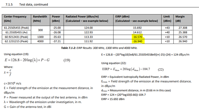
  • When looking 'fcc_47_cfr_part_15_255_subpart_c.pdf' document, there is below table. According to AWR6843(or IWR6843) datasheet, TX power is 12dBm. Considering antenna gain, EIRP should be around 15dBm or a bit higher. However, below table says higher bandwidth has much lower EIRP. How should we interpret this? Also, when I calculate EIRP with below calculation, it should be around 5dBm rater than -16dBm. Could you please clarify more here?  
  • .
  • .
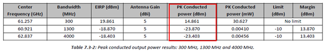
  • Also, when looking below table in same document, PK Conducted power is described as 14.861, -23.870, -23.403dBm. Similar with above question, how could it be so much different for different bandwidth? I should be around 12dBm(TX power of device), right? Do we have numbers that which TX power we used when getting certification?
  • .
  • .
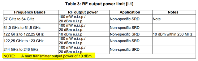
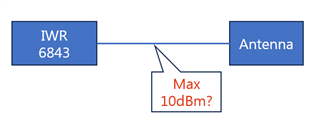
  • When looking 'EN 305 550 - V2.1.0 - Short Range Devices (SRD); Radio equipment to be used in the 40 GHz to 246 GHz frequency range; Harmonised Standard for access to radio spectrum' document, there is below table. What does the highlighted description mean? Does it mean that RADAR device has to limit its output power less than 10dBm? Meaning, EIRP(including antenna gain) limit is 20dBm but RADAR chip shouldn't exceed 10dBm TX power?
  •  

.

Your kind help would be appreciated.

Regards,

Victor Park

  • Hi Victor,

    I would need couple of days to find the chirp configuration that has been used while testing this as the person handling this project is no longer working in TI.

    Thanks,
    Kundan

  • Thanks Kundan! I'll be waiting your update.

    Here is one clarification. Seems IWRL6843AOPEVM was used for the measurement rather than IWRL6843 with PCB antenna. IWRL6843AOP has typical 15dBm power.

    Regards,

    Victor Park

  • Hi Victor,

    The EVM that was used for testing is the 6843ISK board which has 3 patches for a single antenna element (7dBi antenna gain).

    For the above questions,

    • I tried to dig into the configurations that were used while testing this and unfortunately I couldn't find. But from my understanding this could be due to back-off configured and fundamental nature of FMCW signals sweeping rate. The input signal sweeping rate would be much faster than the settling time of the gaussian filter in the spectrum analyzer or EMI receiver. Hence the numbers are different for different bandwidths.
    • Yes the conducted power is limited to 10dBm and the E.I.R.P(conducted+antenna gain) is limited to 20dBm.

    Thanks,
    Kundan

  • Hello Kundan,

    Thanks a lot for your response!

    However, still I and customer couldn't understand why the power has such severe difference based on just little different center frequency and bandwidth. I understand it can be different but it is too much different when looking the numbers where I highlighted.

    According to above data, seems our output power would be much degraded when using larger bandwidth. Could you please clarify my confusion here? When using larger bandwidth, is it general that TX output will be highly degraded?

    Regards,

    Victor Park

  • Hi Victor,

    As per the previous FCC regulations, the ISM band allows 40dBm output power and 10dBm for rest of the band. What I am thinking is we might be using a Tx Back-off in the higher bandwidth modes compared to the 500MHz BW(ISM).
    One more thing which I am suspecting is the FMCW correction factor. Usually, when these measurements are made using a spectrum analyzer or EMI receiver, the input signal sweeping rate would be much faster than the settling time of the gaussian filter in the spectrum analyzer or EMI receiver. To compensate for these measurement limitations, we use FMCW correction factor which is a function of Bandwidth and ramp end time of the chirp. These correction factors will be added to the final readings.
    I am suspecting that the test house might have skipped considering these correction factors.

    No, the output power won't degrade very much when using higher bandwidth chirps. It is the measurement limitation which makes the readings look like this.

    Thanks,
    Kundan

  • Hello Kundan,

    Thanks a lot for the comments!

    Regards,

    Victor Park