Tool/software:
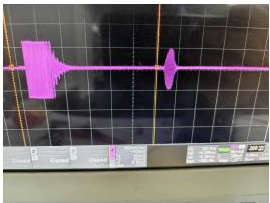
I am currently debugging the PGA460 chip and have encountered the following issues. I hope you can assist me in resolving them. Thank you.Problem description is as follows:I am currently using a burst frequency of 200KHz to drive the ultrasonic sensor and have measured the echo:
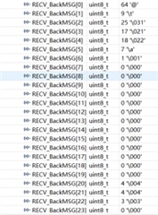
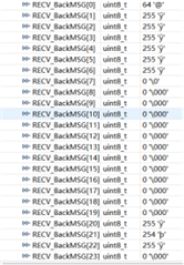
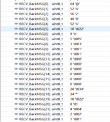
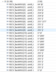
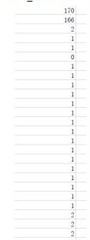
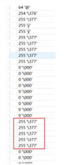
I set the recording time to 8.196ms. When I send the command 0x5505 to read the measurement result, the returned data is: ox40 FF FF FF FF;I then send the command ox5507 to read the echo data, and there are several scenarios:
DP_MUX=0:
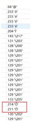
DP_MUX=3:
DP_MUX=4:
Question 1: When I read the measurement result, why does the returned content consist entirely of FFs? What does FF represent?
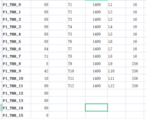
Question 2: When DP_MUX=4, the data seems normal, but when DP_MUX=3, after passing through the bandpass filter, the data appears abnormal. The parameters of the bandpass filter are set to 0xE1, 0x9F, 0xF9, 0xA5, 0x03, 0x2D. Are these parameter settings correct? If not, how should I set the correct parameters?
Question 3: Is Question 2 causing the abnormal measurement results? If not, where might the problem be?