This thread has been locked.

If you have a related question, please click the "Ask a related question" button in the top right corner. The newly created question will be automatically linked to this question.

MMWCAS-DSP-EVM: Enabling MIMO techniques

Part Number: MMWCAS-DSP-EVM
Other Parts Discussed in Thread: TDA2, MMWAVE-DFP

Tool/software:

Hello,

I recently worked on range-Doppler map extraction from the data received by the MMWCAS-DSP-EVM. My final goal is to extract and process data from this device in order to perform post-processing myself, but using all the benefits of this device (the multi-TX property and the possibility to perform elevation sensing with a 2D planar configuration of TX antennas).

However, I don't seem to be able to set up mmWave Studio in order to extract an ADC data file containing what I'm expecting. If I'm using a single TX antenna, I already know how to configure the device in order to have a file with a size of (num_frames * size_of_a_frame), where the size of a single frame is given by (num_adc_samples * num_chirps_per_frame * num_RX_antennas) - from there, extracting the RDC and a range-Doppler map is not trivial, but it has already been done.

How would I set up my device in order to operate in a MIMO configuration? At the moment I'm OK to understand how to set up a single device, in order to see how parameters affect the data capture on a lower scale, and then I will proceed to extend this ina  second moment.

Thanks in advice,

Luca

  • Hi Luca,

    You can refer to the *.lua scripts provided at C:\ti\mmwave_studio_03_00_00_14\mmWaveStudio\Scripts\Cascade.

    Regards,

    Samhitha

  • Hello, it's me back on the thread.

    Looking at the .lua scripts mentioned, and other sources on how the parameters work, I have both good and bad feelings about what I discovered, and what's missing for the picture to be complete. For this reason, I need to ask for more clarification about a couple things.

    Using those files, I seem to have cleared a doubt of mine, about the possible need to set up different chirps, each related to a specific TX channel, and a more complex frame that uses multiple chirps, in order to allow the device to perform MIMO sensing - in fact, the .lua scripts I found have hard-coded relations for 12 different chirps, each related to a specific device and TX antenna, in order to enable 12 parallel TX channels (which is, more or less, what I want).

    Besides, I did not notice any meaningful change in the ADC file related to the data capture, but at least mmWave Studio didn't refuse to work. First question that comes to mind: how should all of this relate to the size of the file I find in the radar SSD? Is there a good way to predict the file size in relation to the number of TX/RX antennas, number of used chirps and ADC samples? In a single-TX scenario, I seem to be able to do this quite easily, but the same can't be said in this case.


    Moreover, while I was implementing this changes into my own Lua code, I stumbled across "advanced frame configuration", opening the door to the concept of "burst of chirps" and "sub-frame" - something I already knew about, but made sure to not mess with, because god bless me it looks convoluted to use (spoiler: it is). Desperate to find a way to make my device work in the way I intended, I started studying what's all of this about, and I surely did not understand everything, but at the very least I was able to wrap my head around what I need to look into next.

    Apparentely, something mmWave Studio does "behind the scenes" is enabling this "advanced frame configuration" every time the device is set up, even in the most trivial of cases, so what it's (probably) expecting from me is a clear indication of this advanced setup, that I need to do myself, in order to create different sub-frames (and not just chirps) assigned to different TX antennas in the device - and that's for sure something I didn't do before, and maybe the whole reason why I did not find a good way to enable MIMO sensing techniques before. What I'm asking is: am I on the right path? Did I understand things correctly? Or maybe have I got something terribly wrong, and I don't actually need all of this?


    One more thing I have to know more about, is all of the "advanced chirp LUT" stuff that is clearly needed as part of the advanced fra,e configuration. I did find something about the sub-frame parameters that need to be set, and how those are intended to work, but I didn't find anything about those mysterious LUTs - not even a mention in the documentation, about what data is supposed to be stored inside. Where can I find anything about this? And, most importantly: how does it relate to the frame configuration?


    Looking forward to a response. Thanks in advice.

    Luca

  • Hi Luca,

    First question that comes to mind: how should all of this relate to the size of the file I find in the radar SSD? Is there a good way to predict the file size in relation to the number of TX/RX antennas, number of used chirps and ADC samples?

    You can refer to the MATLAB scripts provided in the mmWave Studio to understand the format and calculate the size of each bin file.

    Path: C:\ti\mmwave_studio_03_00_00_14\mmWaveStudio\MatlabExamples\4chip_cascade_MIMO_example\utils\dataParse\read_ADC_bin_TDA2_separateFiles.m

    Apparentely, something mmWave Studio does "behind the scenes" is enabling this "advanced frame configuration" every time the device is set up, even in the most trivial of cases, so what it's (probably) expecting from me is a clear indication of this advanced setup, that I need to do myself, in order to create different sub-frames (and not just chirps) assigned to different TX antennas in the device - and that's for sure something I didn't do before, and maybe the whole reason why I did not find a good way to enable MIMO sensing techniques before. What I'm asking is: am I on the right path? Did I understand things correctly? Or maybe have I got something terribly wrong, and I don't actually need all of this?

    In Cascade_Configuration_MIMO.lua file, Advance frame is not used. You need to create your own *.lua script if needed for the Advance frame configuration.

    Where can I find anything about this?

    I suggest you refer to mmwave_dfp_02_02_04_00\docs\mmWave-Radar-Interface-Control.pdf.

    Regards,

    Samhitha

  • Hi Samhitha, thanks for your reply. As I was busy during the weekend, I could put my greedy hands on the topic just now.

    Just as a refresh, because I still don't seem to be able to understand this on my own, even after your kind and exhaustive reply:

    1) is it possible to enable a capture with more than 1 TX antenna without the implementation of the advanced frame configuration?

    2) does the file size match the size of the data cube I parse out from the ADC samples (in terms of number of samples, chirps and antennas)?


    I think I will have to move in little baby steps, because I still don't seem to be able to make a good understanding of every piece of information I need, thus a more focused question. Thanks in advice.

    Luca

  • Hi Luca,

    is it possible to enable a capture with more than 1 TX antenna without the implementation of the advanced frame configuration?

    You can configure each chirp by enabling Tx as per your requirement. As mentioned earlier, you can take a look at "C:\ti\mmwave_studio_03_00_00_14\mmWaveStudio\Scripts\Cascade\Cascade_Configuration_MIMO.lua" to see how it's implemented. It's not required to use advance frame configuration. 

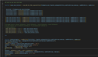
    does the file size match the size of the data cube I parse out from the ADC samples (in terms of number of samples, chirps and antennas)?

    Yes, it should match. Here is a screenshot from the MATLAB script that I have mentioned in my previous reply -

    This code snippet might help you in parsing the raw ADC data that is captured for each device.

    Regards,

    Samhitha

  • Hi, it's me once again.

    In these weeks I discovered the existence of the MMWAVE-DFP, which basically contains a lot of example .exe applications I can use to work with my radar device, and for the moment I'm just experimenting with the mmWave_Cascade_Example. More precisely, inside this folder I found the .exe, which can be used to perform a full data capture with the radar, and a .txt file with lots of parameters, and I'm just trying to get used to how these parameters work, similarly to how I learned to use mmWave Studio.

    I'm happy to report I actually managed to understand how a configuration of multiple chirps per profile interacts with the final size of the ADC file, although I was expecting the data size to be affected also by the number of active TX antennas.

    Unfortunately, that doesn't seem to be the case, and I'm now going to describe what I tried to do, in order for you to find out more quickly something I should have done differently.


    I tried to setup a single chirp derived from profile 0 (start index 0, end index 0), and assigned it to antenna 1, then created a frame with 64 loops and 256 samples using only the single chirp I defined, and as I said before it produced a file of the size I expected it to be - the range-Doppler map extracted from the file was also correct, so that's already a step in the right direction.

    I then created a second chirp from the same profile 0, with start index 1 and end index 1, assigning it to antenna 2 (this time, I also made sure I activated both antennas during the device power-up, in order not to mess up everything - I already had my application crash multiple times, before realizing the problem); then, I modified the frame, in order to use every chirp from start index 0 (the first chirp, assigned to antenna 1) to end index 1 (the second chirp, assigned to antenna 2). Even if I expected the resulting ADC file to be 4 times the size of the previous one (because the number of chirps doubled, but also the number of TX antennas doubled), it was only 2 times bigger than the file with a single TX antenna and a single chirp.

    I simply don't get what's going on here. The file size doubled up, meaning both chirps have been transmitted and received correctly, but the same can't be said for the number of TX antennas, as I'm expecting the number of virtual antennas used by the device to be equal to (num_TX * num_RX) but it keeps behaving as only 1 active TX antenna is used, no matter what.

    Is there anything I missed, or maybe something I did wrong? Thank you very much in advice.

    Luca

  • Hi Luca,

    ADC data size is purely dependent on number of Rx that is enabled (not Tx). Since you are enabling one Tx per chirp, ADC samples of Chirp 0 correspond to Tx0, and samples of Chirp 1 correspond to Tx1.

    Refer to Radar Academy to get a detailed understanding of how Radar works.

    Regards,

    Samhitha

  • Hi Samhitha, thanks again for the reply. This clarified me better on how the ADC file should be handled, and I was kind of wrong in the first place, so now I'm on the right path once again.

    I need help, though, because I tried to setup a third chirp in the same way, assigning it to antenna 2, and modified the frame in order to transmit and receive 3 chirps (start index 0, end index 2), but this time the execution yields an error:

    Sensor Start activation failed with error code -8

    And I don't know what could cause this. In fact, this kind of error is raised even if I try to set only 2 chirps, but using start index 1 and end index 2, which makes even less sense - I imagined it would be related to something expecting 2 chirps to be transmitted, but in this case even which chirps are meant to be transmitted seems to matter too, because the only time this setup produces an ADC capture file is when I set up the frame to use chirps 0 to 1.

    In addition to this, I can confirm that the problem is not related either to which antennas are supposed to transmit the chirps: I can assign each chirp to a different antenna, and the specific antenna used by the chirps makes no difference in the final result, so I'm thinking of excluding any kind of problem related to the transmission of chirps from any antenna in particular.

    As a preliminary debug measure, I already checked, and all 3 TX antennas are activated during device power-on, so it shouldn't be related to this. Besides, if I try to do so, another kind of error is raised, so I'm pretty sure that's not the problem here. And still, the problem remains even if I use only 2 chirps, with a different start index. Looking forward to a response, thank you.

    Luca

  • Hi Luca,

    Check mmwavelink.h file to understand the error codes - mmwave_dfp_<ver>\ti\control\mmwavelink\mmwavelink.h. Since this is a new topic and not related to the initial query (setting up mmWave Studio), I suggest you to create a new E2E.

    Regards,

    Samhitha