Tool/software:
Hi Team,
Customer ask whether this device can reach 100kV/us CMTI, which is from their estimated common mode noise and doesn't show in the datasheet(only typical value here). Could you please help check it? Thanks.

BRs,
Francis
This thread has been locked.
If you have a related question, please click the "Ask a related question" button in the top right corner. The newly created question will be automatically linked to this question.
Tool/software:
Hi Team,
Customer ask whether this device can reach 100kV/us CMTI, which is from their estimated common mode noise and doesn't show in the datasheet(only typical value here). Could you please help check it? Thanks.

BRs,
Francis
Hello Francis,
Thank you for your post.
I am acknowledging your post and I will give you an update tomorrow.
Thank you for your patience,
Joe
Hello Francis,
Thank you for your patience.
We tested the device in a more severe condition than 100kV/µs. The change in the output signal from the CMTI should be less than the listed 200mV of output transients as a result of 100kV/µs.
Best Regards,
Joe
Hi Joe,
So the test condition is > 150kV/us, right? Would like to double check with you.
And would like to ask whether 200mV requirement is from any standard? Thanks in advance.
BRs,
Francis
Hello Francis,
Our test condition is 150kV/us and 200mV is a value of output disturbance that we warranty for less than 1us (with some guard band). CMTI originates from a digital standard based on digital output errors or flipped bits. We are not aware of any official standard.
I hope this helps,
Joe
Hi Team,
Customer ask whether power copper foil can be placed at the bottom of this device? EVM Reference Design doesn't mention it. Thanks.
BRs,
Francis
Hello Francis,
Can you describe the purpose of this power copper foil? I have not heard of this before.
If you can provide an image or example that will also help me understand.
Best Regards,
Joe
Hi Joe,
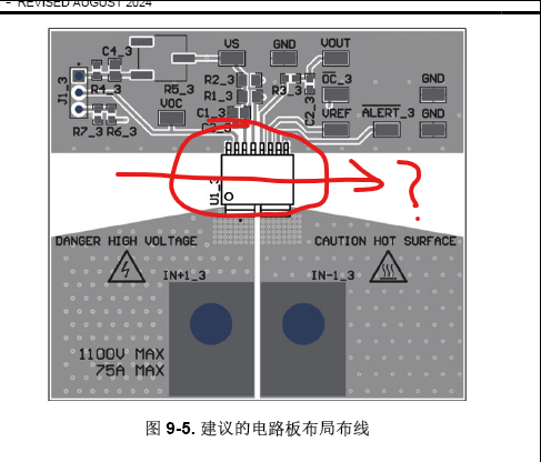
Customer would like to flow current through inner layer board on the red part in below figure.

BRs,
Francis
Hello Francis,
We do not recommend for current to be running underneath the device.
There is potential for capacitive coupling to the LV traces with some traces being parallel to the current as you drew it.
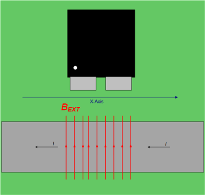
I would recommend running current below the device like this:

I hope this helps,
Joe