This thread has been locked.

If you have a related question, please click the "Ask a related question" button in the top right corner. The newly created question will be automatically linked to this question.

LDC0851: Sensor Triggering Twice

Part Number: LDC0851

Tool/software:

Hello TI Engineers,

We have designed 4 inductive sensor boards with the LDC0851 sensor IC. It is designed on a 4 layer board. The first two layers are LSENSE and bottom two layers are LREF. The design was based of the LDC0851EVM.

All 4 have different outer diameter and inductance value. All 4 use the same Sensor Capacitor at a value of 68pF. The resistors going to the adjust PIN is set to trigger at the furthest distance. The values are based on the datasheet. 

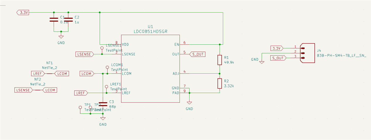
Below is a schematic of all 4 since they only vary with the coil trace in the layout

Below is a table of the PCB version, coil diameter and inductance. These are all designed with coil designer web bench form TI

 PCB Version

Inductance

Diameter and Turns

Coil Trace and Spacing

 V5

 9.075uH

16mm 15 Turns

 0.178mm / 0.178mm

V5b 

14uH

20mm 17 Turns

 0.203mm / 0.203mm

 V6

 28.263uH

25mm 21 Turns

0.203mm / 0.203mm

V7

31.04uH

30mm 20 Turns

0.254mm / 0.254mm

Version 5 was fully assembled by an SMT house . For the Versions 5b to V7, we ordered bare boards and hand soldered them ourselves. I do not know if the issue we are seeing is because of the hand soldering or a design issue. We did have previous issues of the sensor not actually working, but some assemblies worked right away.

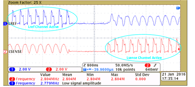
The issue we are seeing is the on all Version 5b to V7 PCBA that we assembled that is functioning. Functioning means, when there is no metal, the output is 3.3V and with the presence of a metal the output drops to 0V. We built a circuit similar to the EVM where an LED turns ON then the sensor Triggers.

What we are seeing is that Versions 5B to V7 are triggering twice with V7 having the worse double trigger response.

Our test setup is that we have a metal plate that is significantly larger than largest diameter PCB design that we have. 

For version 5B and 6. When we bring the metal closer it first triggers (LDC0851 output goes from 3.3V to 0V) then it un-triggers (output goes to 0V back to 3.3V) as we bring it closer, then triggers back all the way until the metal plate touches the PCB. I do not have the exact measurement of the distance but I were to express from 0 to 100 (0 is when the PCB and metal plate touches and 100 is the first time it triggers), below is the range

V5B

1. 100 to 80 - triggers

2. 80 to 60 - un-triggers

3. 60 to 0  - triggers

V6

1. 100 to 70 - triggers

2. 70 to 40 - un-triggers

3. 40 to 0  - triggers

For V7, it sometimes un-triggers twice and it un-triggers when the metal is touching the PCB.

When the metal is cover the full coil, it un-triggers but when I move the metal such that it is covering only half the coil, the sensor gets triggered.

For Version 5, all 10 PCBAs that were SMT machined only triggers once. 

Can these double triggering issues be related with the hand soldering? Or is combination of increase in diameter and inductance value playing a part in this issue? Or a combination of all 3? (hand soldering, diameter and inductance value). Let me know if you need more details on the design. The measured inductance on the assembled PCBs we have tested are close to the designed value by 2-3uH.

Is there an an ideal coil fill ratio? Is there a recommended distance between edge of the PCB and the coil or distance between the coil and the rest of the circuit? Aside from the side of the coil that has the other components there are no components on the other sides of the coil similar to the EVM.


Thanks,

Deniel

  • Hello Deniel,

    It is possible this is related to hand soldering or possibly incorrect component population, but would like to know more information.  

    Are the LSENSE and LREF coils well matched?  You mention one inductance, but the LDC0851 works on a comparator type of methodology where the difference of LSENSE and LREF are compared.  Can you measure inductance of both coils with respect to LCOM?  If you have assembled boards, you can also look at the resonant frequency of both.  

    Are your coils side by side or stacked?  

    The app note below offers some troubleshooting tips.  I recommend checking your waveforms and comparing with figure 6.  Also, check section 4 and ensure that the layers and orientation is correct.  

    https://www.ti.com/lit/an/snoa956/snoa956.pdf 

  • Hello Eddie,

    Here is a table of the inductances and resonant frequency of each setup that we have. We also got data from the EVM

    Serial number Diameter LSENSE LREF LSENSE Freq LREF Freq
    EVM 20mm 6.8 6.8 9.628MHz 9.628MHz
    SN1 16mm 10.31 10.28
    SN2 16mm 10.26 10.28 ~7MHz ~7MHz
    SN8 20mm 15.6 15.7 ~5MHz ~5MHz
    SN3 25mm 30 30 ~15MHz ~15MHz
    SN10 25mm 30.3 30
    SN4 30mm 33.5 33.5 ~12MHz ~12MHz
    SN8 30mm 33.27 33.27

    All sensors have the same inductance value in LSENSE and LREF. 

    The resonant frequency are still within the spec of the IC

    The EVM and sensor with 16mm diameter are the only ones not triggering twice 

    Some additional questions I have:

    1. With the waveform of the LREF and LSENSE:

    A. Should the square wave of LSENSE be to the right of the Sinusoid part and Flat Part?

    B. Should the square wave of LREF be to the left of the Sinusoid part and flat Part?

    Here my additional observations

    The EVM and 16mm diameter sensor have the LSENSE and LREF Waveforms similar to the Normal Waveform in Figure 6 (image above)

    The 20, 25 and 30mm diameter sensor have a Flipped Version of the LSENSE and LREF meaning

    The LSENSE has the square wave followed by the flat no signal area followed by the sinusoid

    The LREF has the sinusoid followed by the flat no signal followed by the square wave

    In addition to that information, the square wave of the 30mm is not a clean square wave. It has some parts that look sinusoidal.

    After looking at the layout design I noticed I flipped the overall spiral directions on the 20, 25 and 30mm

    The spiral of the 16mm followed the EVM which follows the recommended coil orientation and polarity on Figure 9 of the troubleshooting notes

    1. Counter-Clockwise Out Spiral on Layer 1

    2. Clockwise Out Spiral on Layer 2

    3. Clockwise Out Spiral on Layer 3

    4. Counter-Clockwise Out Spiral on Layer 4

    The 20, 25 and 30mm designs follow the following

    1. Clockwise Out Spiral on Layer 1

    2. Counter-Clockwise Out Spiral on Layer 2

    3. Counter-Clockwise Out Spiral on Layer 3

    4. Clockwise Out Spiral on Layer 4

    Do you think the reverse of orientation of the coils cause this issue? I thought as long as the top and bottom layer coil orientation are the same and the inner layer coil orientation are the same that should be good enough.

    Thanks,

    Deniel

  • Deniel,

    Thanks for the additional information.  You are correct that the orientation of the coils just needs to have the inner layer and top/bottom layer orientation the same.  In regards to the signal measurements, you should see the active channel with a square wave and inactive channel with sine wave.  Could you please post scope shots of the signals that you see on each coil?  

  • Hello Eddie,

    I will get screenshots of the signals from each coil of the different sensors. I will update this thread once I get the data.

    While I am doing that, What do you mean by active and inactive channel? Is this the LSENSE and LREF?

    Thanks,

    Deniel

  • That correct.  Only one channel is actively driving each coil at a time.

  • Hello Eddie,

    I made a new version PCB for all 3 different Sensor Diameters. This time I followed the Coil direction based on Figure 7-11 on the LDC0851 Datasheet.

    All 3 versions of the coil are working properly now and does not show issue with un-triggering when the metal is closer to the sensor. 

    We still have the 3 diameters of 20mm, 25mm and 30mm. All 3 have similar inductance of 10uH. LREF and LSESNSE have the same measured inductance. 

    The only issue I am seeing now is the max distance I am able to sense in the 25 and 30mm.

    Below is a table of of max sensing distance with how many sensors have been assembled for each version of the coil diameter

    Sensor Diameter Quantity Made Max Sensing Distance
    20mm 2 4mm
    25mm 5 4.5mm
    30mm 6 3.5mm

    I was expecting the 25mm to be triggering at 5mm and the 30mm to be triggering at 6mm. I am using the same resistors for the ADJ pin on all 3 boards. The schematic and components are the same for all 3. The only difference is the coil diameter.

    What do you think is the reason why I am sensing a lower max sensing distance with the higher diameter coils? 

    Thanks,

    Deniel

  • Deniel,

    Glad to hear the new boards are functional.  Are Q factors similar for all coils as well?  You can use the tool below to calculate this if you are not already using this tool.

    https://www.ti.com/tool/LDC-DESIGN-TOOLS     

  • Hello Eddie,

    Is there a Q factor level that we need to target?

    Thanks,

    Deniel

  • Deniel,

    We don't have  specific range of Q for the device that is required.  In general, a higher Q is better since the LC tank acts as a bandpass filter and will allow for more outside frequencies to be filtered.  Higher Q can also help increase range some.  Typical values may be from ~20 - 80.  If you can target the upper range, this should help.  The Q is affected by both trace width and resonant capacitor, so you may be able to decrease the capacitor value to increase your Q without having to design a new coil.

  • Hello Eddie,

    Thanks for the clarification on the Q Factor. I adjusted the Resonant Capacitor by decreasing it from 68pF to 39pF. The sensing distance of the 30mm, which was already low to begin with (3.5mm), decreased to below 3mm (around 2.5mm). 

    Also the 20-30mm coil designs that I mentioned above also use the same 68pF resonant capacitor. 

    Is there other ways to approach the sensing distance issue at the larger coil diameter?

    Thanks,

    Deniel

  • Deniel,

    That seems a bit odd that the range was reduced when increasing the Q.  Can you provide the spreadsheet with your parameters?  I would like to know specifically what the Q was with each capacitor.

  • Hello Eddie,

    Below is the screenshot of the how we designed the coil using the coil designer webench from TI. Let me know if you need more information from me. This is with the 25mm coil design. I have qty: 30 pcs of inductive sensor that has the 25mm diameter and has the 68pF. This was all assembled by a PCB House.

    From my previous responses above, we had qty: 5 pcs of the 25mm diameter sensor that we assembled with our reflow oven. These resulted in a 4.5mm sensing distance. These 5 had the 68pF capacitor on LCOM.

    On the 30 pcs that we had manufactured outside with an actual SMT machine, all 30 were only triggering at most at 3mm. Some were even triggering below 3mm. When we reworked 13 out of 30 by changing the LCOM capacitor from 68pF to 100pF,

    all 13 now triggers always at 4mm. 

    8 out of 13 triggers up to 4.5mm

    3 out of 8 triggers up to 5mm

    2 out of the 3 triggers up to 5.5mm

    Thanks,

    Deniel

  • Deniel,

    That seems like a large distribution of the range observed.  Are you able to measure the inductance and Rp of the boards?  This can be done with LCR meter or network analyzer.  You should measure from Lcom to Lref and Lcom to Lsense.  It will be interesting to see what variance you see between PCB's.  If there is a larger difference between Lcom and Lsense, there can be a smaller range compared to boards where the inductances are more consistent.