This thread has been locked.

If you have a related question, please click the "Ask a related question" button in the top right corner. The newly created question will be automatically linked to this question.

AWRL6844EVM:Wavelength Calculation Basis for λ/2 and λ in Virtual Antenna Array

Part Number: AWRL6844EVM
Other Parts Discussed in Thread: AWRL6844

Tool/software:

Hello,

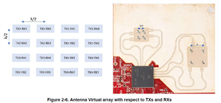
In AWRL6844 EVM, I am referring to Figure 2-6, which illustrates the antenna virtual array with respect to TX and RX elements.

The diagram indicates that the element spacing is set at λ/2 and λ.

I would like to confirm whether these values are calculated based on the free-space wavelength or if they should be determined using the guided wavelength (taking into account the permittivity of the PCB substrate material).

Since the antenna is implemented on a PCB, should the half-wavelength (λ/2) and wavelength (λ) be adjusted according to the effective permittivity of the substrate, or is the free-space wavelength used in the design and interpretation of the virtual array?

I appreciate your guidance on this matter.

  • Hi Hyungu Jeon,
       
        λ/2 spacing is set in the PCB where λ is calculated based on the center frequency of antenna simulation. Which is in this case is 59GHz.

    Thanks and Regards,
    Sivaprasad

  • Thank you for your response.

    I have a few additional questions.

    Most RF results I have come across mainly provide radiation pattern data, but I rarely see discussions or measurements regarding S-parameters.

    Is it unnecessary to check S-parameter characteristics in this case? If so, could you explain why?

    Additionally, I am curious about the design criteria for the transmission line length.

    What factors determine the length of the transmission lines in this design?

    I appreciate your insights on these points.

  • Hi Hyungu Jeon,

        It is necessary to check S-parameters while designing the antenna. From antenna simulation perspective, you need to keep transmission line length as short as possible to reduce trace losses and 50 ohm impedance matching should be there between patch and trace. If you are having multiple antenna elements, then you need to take care, the length of transmission lines as well

    Thanks and Regards,
    Sivaprasad