This thread has been locked.

If you have a related question, please click the "Ask a related question" button in the top right corner. The newly created question will be automatically linked to this question.

LDC1101: Big spikes in sensor measurements

Part Number: LDC1101


Tool/software:

Hello community,

in my application I have a board that embeds LDC1101 following the layout and guidelines of the dedicated Evaluation Module (LDC1101EVM).
The board is connected via twisted cable (length=2.5 cm) to a planar inductance of 23 uH (measured) and a capacitor section .

The capacitor section is made up by three capacitor footprints in parallel (for calibration purpose).

The sensor is a 6 cm x 6 cm inductor with track width of 0.5 mm and 1 mm (center-center) of spacing (0.5 mm effective).

Now, I experienced the following cases:

  • The planar inductor with a capacitor of 1200pF C0G and 2 empty footprints is quite noisy but works (datalog S1 freq (Hz) in the figure below).
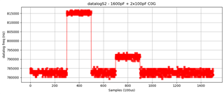
  • The planar inductor with a capacitor of 1800pF C0G and 2 empty footprints is quite noisy and in general works but I register several big spikes (see datalog S2 freq (Hz) in the figure below).

More information:
The same inductor with no calibration footprints works quite good (reduced variance and no spikes). 

The planar inductor with a capacitor of 1800pF C0G and 2 empty footprints is quite noisy but works (no spikes) when a metal target is present.

Can someone help me with it?

Thanks a lot,
Giovanni

  • Giovanni,

    Sorry to hear you are having challenges with your board.

    How did you arrive at the coil design and capacitor values for your sensor?

    1. What sensor frequencies do you expect with the different capacitor values when you populate the footprints?
    2. Do you see signals close to those frequencies when the footprints are populated?
    3. Are the sensor signals' amplitudes close to the recommended values?

    regards,
    John

  • Dear John,

    thanks for your reply. I try to answer point-by-point.

    How did you arrive at the coil design and capacitor values for your sensor?

    Via design tool provided by TI and simulation with EM solver. Then, I measured inductance with LCR meter over frequency and found good agree with simulation. I also studied the Cpar of the L via self-resonating response.


    What sensor frequencies do you expect with the different capacitor values when you populate the footprints?

    The purpose of those footprints is to center the frequency around a specific value with a tolerance. They are calibration capacitors (order 20-30pF typ.)


    Do you see signals close to those frequencies when the footprints are populated?

    Since the median frequency is correct (excluding spikes) I never tried to populate them to calibrate the value. I'll try. But I cannot understand why uncovered pad can create this problem at that specific frequency. For example, it is interesting that I don't experience the same problem at  950 kHz (datalogS1) .

    Update: I tried to populate all the 3 footprints (1800pF = 1600pF +2x100pF) and the readings seems better now!
    But - exactly - why exposed pads generate such spikes?


    Are the sensor signals' amplitudes close to the recommended values?

    Yes, I checked it with oscilloscope. 

  • Giovanni,

    I don't think the unpopulated pads themselves are the culprit, but let's be sure by looking at the sensor waveform as you populate the pads.

    1. What is your desired sensor waveform amplitude & frequency?
    2. What are the inductance and capacitance values you use to get the desired sensor signal?
    3. What is the sensor waveform amplitude & frequency as you add parts to the pads?

    Another consideration might be noise on the device VCC lines.
    Can you power the LDC1101 from a separate power supply?
    If so, does the behavior chnage?

    Regards,
    John

  • Hi John,

    The desired frequency is approximately 782 kHz, based on the LHR measurements in the previous figure, with C = 1800 pF and L = 23 µH, as expected.

    When I place the oscilloscope probes in differential mode on INA and INB, I measure 0.85 Vpk at a frequency of 774 kHz, possibly due to Cosc.

    The frequency and amplitude remain unchanged with or without the empty pads. I do not observe any clear modifications—via oscilloscope—to the frequency or amplitude when spikes occur.

    The VCC line of the LDC exhibits a maximum ripple of 70 mVpp superimposed the 3.3V (switching at 100 kHz). Bypassing the VCC lines and connecting them to a stabilized power supply does not result in visible improvements in the waveform or measurement results (without populated calibration footprints).

    Regards,
    Giovanni


  • Giovanni,

    It sounds like the input signal is okay.

    Would it be possible to increase your sensor frequency to see if you still see the spikes on your output?

    Regards,
    John

  • John,

    The same board with a frequency of ~1MHz with a C = 1200pF does not exibith spikes even if there areunpopulated footprints. Using a single 1200pF with 2 empty footprints, or 1000pF+2x100pF does not show any difference.

    I tested that the spikes happens for frequency < ~900 kHz.


    Giovanni

  • Giovanni,

    No potential root causes are obvious at this point, but the fact you don't see any spikes at higher sensor frequency is probably a clue of some kind.

    Can you move to a higher sensor frequency for your application?
    If not, and the lower sensor frequency is a must-have, can you try increasing the conversion time? If you can do this, does it change the "spike" behavior?

    Which configuration are you using, and what are the device settings you are using (as called out in data sheet section (9.1)?

    Regards,
    John

  • Hi John,

    The frequency is a must-have as well as the sensor query time = 100 µs.


    Please find attached the LDC regs configuration for the LHR measurements:

    RP_SET (0x01) -> 0x75

    • HIGH_Q_SENSOR -> b0 (since we have ~19)
    • RP_MAX -> b011 (does not matter, I referred to the default in LDC DS example)
    • RP_MIN ->  b101 (since Rp is ~ 2.2kOhm)

    DIG_CONFIG(0x04) ) -> 0x43

    • MIN_FREQ  -> b0100 (since with fmin 700 kHz MIN_FREQ = 4.57)
    • RESP_TIME -> b011 (does not matter, I referred to the default in LDC DS example)

    RCOUNT(0x04) ) -> MSB = 0x00; LSB= 0x19

    I know that this value is low and can lead to high variance in measurements, but it comes from some tests I conducted. I query the sensor every 100 µs, and I found that with an RCOUNT higher than this, the LDC sometimes returns zero as a measurement.

    Regards,
    Giovanni

  • Hi Giovanni,

    John is currently out of office. He will be back on Monday, so he should be able to take a look at your question then.

    Best,

    ~Alicia

  • Giovanni,

    Has the Rs or Rp been measured for your sense coil and inter-connects?

    I re-scanned this thread and didn't see any mention of the operating mode. Which mode are you using?

    Regards,
    John

  • Dear John,

    as mentioned in my previous post LHR measurements. Rp has been measured as 2.2kOhm.

    Sincerely,
    Giovanni

  • Thanks Giovanni.
    I missed that (1st day back from vacation, ;-)).

    I will dig into this some more and update this thread by COB on Thursday.

    Regards,
    John

  • Giovanni,

    What reference clock frequency are you using?

    Regards,
    John

  • John,

    16MHz stable with duty cycle 51.3% via TCXO.


    Regards,
    Giovanni

  • Thank you Giovanni,

    I will look into this further and update this thread tomorrow.

    Regrads,
    John

  • Giovanni,

    I'm wondering if output variability you are seeing is due to too few sensor waveform cycles being captured during the conversion time.

    The duration of a sensor waveform is Tsensor = 1/782kHz = 1.279usec.
    The LHR conversion time (eqn. 14): tCONV = (55 + 16·RCOUNT)/fCLKIN = (55 + 16·25)/16MHz = 28.4375usec.
    But I think you only collect sensor samples over an RCOUNT number ref clock cycles, so the actual sample time would be:
    Sample time = (16·RCOUNT)/fCLKIN = 400/16MHz = 25usec.

    So the sample time is allowing the device to capture ~19.5 cycles of the sensor waveform.
    Ordinarily I'd think that should be enough for a reliable reading, but perhaps that is leading to the variance on the output.

    Could you please try some larger RCOUNT settings - with your desired sensor frequency - and see if that improves the output behavior?

    Regards,
    John

  • Dear John,

    Could you please try some larger RCOUNT settings - with your desired sensor frequency - and see if that improves the output behavior?

    I tried with RCOUNT = 0x30 and spikes dissapear but sometimes it returns 0. I can't increase the RCOUNT a lot since my sensor query interval is 100us.

    Could those spikes be due to external disturbances? The environment in which the sensor operates is quite noisy, but other sensors of the same family have not given similar problems. I have tested at least twenty of them.

    Would it be possible to place a "bandpass" filter between the LDC1101 and the LC tank? What do you suggest in this case?

    Giovanni

  • Giovanni,

    If the output spikes are caused by external noise, I would expect it to show up more broadly, such as in other devices and/or different settings for the same device.
    You might be able to test this hypothesis by using a leadless inductor in place of the sensor - and maybe adjust the PCB capacitor - so that you get the same sensor frequency, and then look for the output spikes. 

    There's some critical interactions between the LDC device and the LC sensor that help sustain the sensor's oscillation. 
    While I haven't seen an example of a bandpass filter on the input path, I suspect BP losses would compromise the oscillator formed by the LDC & LC sensor.

    It sounds like there are some constraints on the sensor's measuring interval and the sensor frequency. 
    What happens if you increase the sensor frequency & RCOUNT to the max permissible values? Will that support your application and minimize the output spikes?

    Also, how does the sensor waveform look when there are spikes and no spikes?
    One trick we use is to place a leaded 1k resistor between the tip of a high impedance oscope probe and the PCB test point.
    This helps reduce the capacitive loading of the probe.

    Regards,
    John

  • John,

    If the output spikes are caused by external noise, I would expect it to show up more broadly, such as in other devices and/or different settings for the same device.

    You are right!


    With a higher frequency (~1MHz) and a RCOUNT 0x30 there are no spikes and the variance is actually contained.
    The problem seems to be related to lower frequencies.
    This supports your theory. Unfortunately the frequency and the query interval are must-haves and I cannot change them.

    Thanks for the advice about the probes.
    However I do not see clear differences in the waveform in 10 ms of observation.


    Giovanni

  • Giovanni,

    This will sounds like a weird question, but do the spikes happen in the same time/location on the output, or does it vary from measurement-to-measurement?

    Regards,
    John

  • John,

    believe me, checking the periodicity of the error was one of the first things I investigated.
    Unfortunately I did not find periodic or repetitive patterns.
    The only thing I noticed is that immediately after a peak towards higher frequencies, I found one towards the bottom at a distance of one sample (100us), as a bounce of the measurement.


    The thing that drives me crazy is that this strange behavior only occurs with antennas with the empty footprints as I previously told you.

    I think something must concern this setup (since I also changed LDC and TCXO several times), but I can't understand what could cause this problem!


    Anyway, I want to thank you a lot for your support.


    Regards,
    Giovanni

  • John,

    I noticed another huge problem with the same sensors that gas those spikes.

    When working with the LDC at -20 degrees I read an exaggerated frequency shift (about + 100kHz). This problem is not present on another sensor on the same board which however works at higher frequencies (about 1 MHz).

    What could have caused such a large shift in frequency on that sensor?

    Sincerely,

    Giovanni