


Tool/software:
Hi,
I am currently testing and analyzing the Long Range People Detection example from Radar Toolbox 2.10.
The sensorPosition CLI command is used to set the sensor height, azimuth, and elevation tilt values.
However, the sensor output(Point Cloud and Target X,Y,Z) does not apply the sensorPosition command value; instead, it outputs coordinates based on the Radar's field of view (FOV) reference frame.
Additionally, I found that the Industrial Visualizer code uses the sensorPosition command value to perform coordinate rotation.
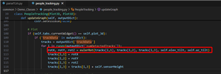
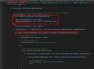
I have examined the Gtrack algorithm code and found that when the azimuth tilt is not zero, the point cloud coordinates are transformed into the world coordinate system.
However, I did not find any transformation applied to the boundaryBox coordinates.
My Questions:
- Does the sensor's UART output (Point Cloud and Target X, Y, Z) not apply the
sensorPositioncommand value? - What is the purpose of transforming coordinates into the world coordinate system in Gtrack?
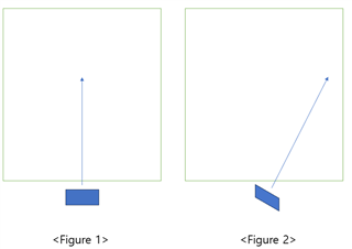
- When estimating objects in Gtrack, which shape is used for the boundary box among the following illustrations?
Thanks.
