This thread has been locked.

If you have a related question, please click the "Ask a related question" button in the top right corner. The newly created question will be automatically linked to this question.

AWRL6432: Strange power consumption issue.

Part Number: AWRL6432

Tool/software:

Hi specialists:

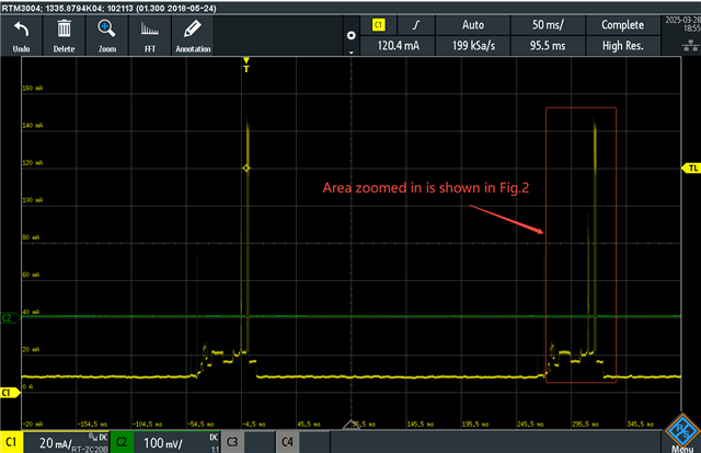
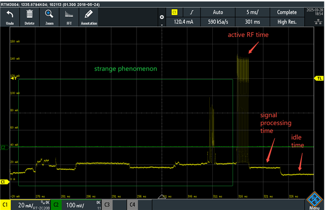
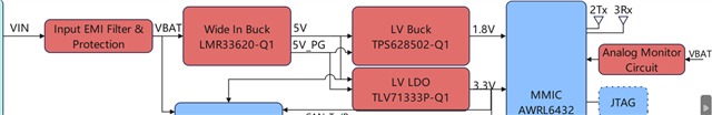
Now I configure AWRL6432 as Low-power mode and observe the current using oscilloscope. (See Fig. 1) The period of RF active (red) and signal processing (blue)can be observed, however, there is a period (green) in which current is larger than that of signal process. Is it reasonable? Thank you!   (Now my hardware is 3.3 V IO Mode & BOM Optimized)

Fig 1. current measured by oscilloscope


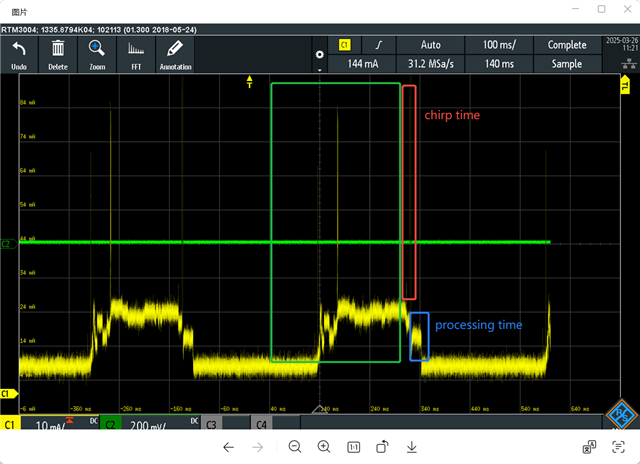
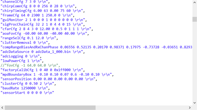
Fig. 2  our waveform configuration 

Regards, 

Stan

  • Hi Stan,

    Can you confirm whether the current plot is of 1.8V rail or 3.3V rail?

    Thanks.

  • Hi Voona:

    The current plot is measured by VDD(12V) rail. In addition, our SDK version is 5.4.0.1.

    Regards, 

    Stan

  • Hi Stan,

    We cannot easily classify the active, processing and idle time based on VDD supply. Please plot the 1.2RF current to understand the correct Active RF time (which includes chirping). Lowest current consumption that you see in the VDD current plot is the least power consuming state. The time between this least power consuming state and active state is the processing time. Hope this helps!

    Thanks.

  • Hi Voona:

    Thanks for suggestion and we will provide a more clear plot for you. As you mentioned, lowest current consumption in the VDD current plot is expected as the least power consuming state. However, it's stranger that power consuming becomes large in the end of period of idle state. Could you help to investigate after I provide a more clear plot?

    Thanks

    stan

  • Hi Stan,

    Sorry, I could not get your question on the part where you are mentioning about "power consuming becomes large in the end of period of idle state". Can you please elaborate more on this question, or we can also discuss this once we get the clear plot.

    Thanks.

  • Hi, Voona:

    I zoom in the current plot which may provide you more information. Fig. 1 shows the area is zoomed in .

    In Fig. 2, it can be observed that there are 8 chirps in active RF time followed by signal processing time and idle time. 

    Also, it can be found that the current level in some period (green box) is larger than that of signal processing time.

    I am confused why the current level is not be as low as that in idle time. Thanks. 

    Regards,

    Stan


    Fig. 1
       

    Fig. 2


  • Hi Stan,

    Thanks for sharing the 1.2RF plots. Can you confirm whether the above plots are taken from the AWRL6432 BOOST EVM and are measured just before the pins of radar device?

    Thanks.

  • Hi Voona:

    The above plots are taken from our design radar product using AWRL6432. 

    Maybe I can measure the current from the AWRL6432 BOOST EVM and do comparison.

    Regards, 

    Stan

  • Hi Stan,

    • Can you please confirm whether your design is 3.3V I/O Power optimized mode? 
    • Can you share the power topology that you have used in your system? Are the supplies provided to radar devices being fed to different components in the system? 
    • If you are using BOM opt. mode, then we should be looking at 1.8V rail plot. Because 1.2RF voltage and 1.2V digital supplies are internally generated here and we should not be worried about VDD and 1.2RF power rails. If so, could you tell how are you measuring the current in BOM opt. mode? 
    • Are you using all the recommended capacitors at power supply pins? 

    Thanks.

  • Hi Voona:

    My feedback is as follows:

    1. My design is 3.3V I/O BOM Optimized.
    2. Sure. The power topology is shown in the following Fig.


    3. The measure is set up as follows. The rail is VDD and the current probe is R&S RT-ZC20B


    4. Yes.

    Regards,

    Stan

  • Hi Stan,

    Thanks for confirming that your mode of operation is 3.3V BOM opt. mode. For 3.3V BOM opt. mode, we should not be looking at VDD and 1.2RF rail plots. Rather we should be looking at 1.8V rail plot. Apologies for the confusion before. Please provide the 1.8V rail plot where we can help you with classifying Active, processing and idle regions.
    Could you please tell what is your end application and who is the end customer?

    Thanks. 

  • Hi Voona:

    Thanks for quick reply.

    I'll provide 1.8V rail plot later. Could you tell me why we should not be looking at VDD? 

    Our product aims for intruder detection. Regarding the end customer, please forgive me for being unable to disclose this information.

    Regards,

    Stan

  • Hi Stan,

    For BOM opt. mode, VDD and 1P2RF supplies are generated internally from 1.8V power rail. Hence, we should be looking at 1.8V rail plot.
    Can you help us understand why you are looking at the current plots? Are you facing any performance related issues?

    Thanks.

  • HI Voona:

    Thanks for your explanation. 

    Due to the customer's strict requirement that the current must not exceed 7mA, we currently have to rely on reducing the frame rate to meet this target. However, this significantly impacts the radar's detection and tracking performance. Therefore, we are now looking for a solution that can balance both frame rate and low current consumption. During our exploration of new approaches, we noticed that there is a considerable amount of power consumption before entering the active time, which we suspect may be caused by the wake-up process. If we can reduce the power consumption during this phase, it might be possible to shorten the frame period. This is the reason why I brought up the question to seek advice from the TI expert.

    Regards,

    Stan

  • Hi Voona:

    Here is the 1.8V rail plot (Fig. 1). It can be observed that the shape of the 1.8V rail is nearly identical to that of the 12V rail (from the previous plot), except for the scaling.


    Fig. 1  

    Regards,

    Stan

  • Hi Stan,

    Can you please confirm that the 1.8V plot you have shared is not for the first frame?

    Thanks. 

  • Hi Voona:

    This is indeed not the data from the first frame. We measured the 1.8V rail current after the radar had been running for some time.

    Regards.

    Stan

  • Hi Stan,

    Are you performing any calibrations/ monitoring here? Also, could you confirm if this test is done at constant temperature?

    Thanks.

  • Hi Voona:

    1. I do nothing change (incl. any calibrations/monitoring) but run Ti's Intruder demo with the costumed profile (shown as above). 
    2. Yes. It is done at constant temperature
    3. I also check the document (https://www.ti.com/lit/pdf/swra754). As mentioned in that document, it typically takes around 2ms to reinitialize the SW after coming out of a deep sleep period, depending on the options selected. This is quite different from our situation (If the strange situation is due to wakeup.
    4. Could you kindly provide Ti's self-test current plot of 6432's low-power mode for us as a benchmark?

    Regards,

    Stan

  • Hi Stan,

    • Could you please confirm the same 1.8V rail behavior is observed across all frames?
    • Are you using intruder demo from radar toolbox? If so, what is the radar toolbox version?  

    Please find our 1.8V rail plot of AWRL6432 device for 3.3V BOM opt. mode.

    Thanks.

  • Hi Voona:

    Thanks for your plot. In this figure, the current behavior appears much more reasonable. 

    • The behavior is the same across all frames during observation (about 2 min.)
    • No. I use the following framework for intruder development
      • SDK: MMWAVE_L_SDK_05_04_00_01
      • demo: motion_and_presence_detection
         (<PACKAGE_LOCATION>\MMWAVE_L_SDK_05_04_00_01\examples\mmw_demo\motion_and_presence_detection)

    Could you kindly provide the SDK/demo/configuration used for your provided plot? Maybe I repeat the experiment under the same conditions and see if the current plot is the same.

    Regards,

    Stan

     
  • Hi Stan,

    Please use motion and presence demo from the latest SDK available at MMWAVE-L-SDK Software development kit (SDK) | TI.com

    You should observe the same current signature on your side at 1.8V rail. 

    Can you please reconfirm that 1.8V supply generated from the LV-Buck in your system is only provided to 1.8V pins of AWRL6432 and nothing else?  

    Thanks.

  • Hi Voona:

    We use the latest SDK and measure the current. The current behavior is near the same with yours. 

    Thank you very much for your continuous and enthusiastic support in providing directions for troubleshooting.

    Regards,

    Stan