This thread has been locked.

If you have a related question, please click the "Ask a related question" button in the top right corner. The newly created question will be automatically linked to this question.

LDC1101: Stuck in Reset Mode - Status Register Shows 0x00

Part Number: LDC1101

Tool/software:

I’m trying to use the LDC1101 with a Raspberry Pi 4 Model B, but the device seems stuck in reset mode. The Status Register keeps reading 0x00 (reset mode), and it doesn’t change to 0x02 (active mode), even when I set the FUNC_MODE register to 0x02.

I've already tried these:

  • Double-checked the SPI connections (SCK, MOSI, MISO, CS).
  • Set the FUNC_MODE register to 0x02 for active mode.
  • Verified the 3.3V and GND connections are correct.
  • Tried resetting the device multiple times, but it stays in reset.

Here are the issues I'm experiencing:

  • Status Register is stuck at 0x00.
  • Inductance Data is always 0.

Has anyone faced this problem before? Any tips on what might be causing the LDC1101 to stay in reset mode, or what I might be missing in the setup?

  • Joseph,

    Thanks for your post, and sorry to hear your're having problems.

    I will look into your questions and will update this thread by Tuesday of next week.

    Regards,
    John

  • Hi John,

    Thanks for your response. I’ve had a chance to look into the issue further, and I noticed that all the registers are returning 0 except for the following:

    • 0x01: 2
    • 0x02: 144
    • 0x08: 88
    • 0x09: 2
    • 0x0B: 1
    • 0x20: 124

    However, the RP Measurement is still stuck at 31744. In general, all of the registers does not change their value.

    I thought I’d share this update in case it helps narrow down the issue. I’ll continue investigating and will keep you posted.

    Looking forward to your feedback.

  • I think I’ve identified a potential issue related to the LHR_STATUS register. From what I’ve observed, it seems to be stuck at 0x01, which might be causing the device to remain in reset mode and not transition to active mode.

    So far, we’ve seen that:

    • The Status Register consistently reads 0x00, indicating reset mode.

    • The FUNC_MODE register has been set to 0x02, but the device doesn’t exit reset.

    • Other registers (such as RP measurement and LHR-related ones) remain unchanged, and inductance data is stuck at 0.

    It could be that something in the LHR configuration is preventing proper initialization. Just thought I’d add this info to help narrow down the root cause.

    Looking forward to any further suggestions!

  • Joseph,

    Is it possible for you to compare the behavior you are seeing with the same device settings etc. while using our GUI?
    If possible, it might give some add'l reference points for comparison. 

    Also, would it be okay to address all of your questions on this thread since they seem to be related??
    It gets a little challenging to manage multiple, related threads.
    If that's okay I will close the other thread and we can move forward on this one.

    Regards,
    John

  • Hi John,

    Unfortunately, I don't have the EVM board to use the GUI — I’m using the LDC1101 Click Board (MIKROE-3240). I’ve managed to get the RP+L mode working but can only read valid RP_DATA. The L_DATA seems stuck at a constant value, and in LHR mode, I only get zeros from LHR_DATA.

    I suspect I might be missing some register configurations. Could you please share the required register settings to properly access LHR_DATA?

  • Joseph,

    An export of the register settings from the LDC1101 EVM are attached to this thread as a .txt file.
    It gives just the register name and the setting, so I've included two snaps of the GUI's register panes that give a little more info.

    I hope it helps. 

    Regards,
    John

    LDC1101 EVM Registers_RP_SET	07
    LDC1101 EVM Registers_TC1	00
    LDC1101 EVM Registers_TC2	00
    LDC1101 EVM Registers_DIG_CONF	07
    LDC1101 EVM Registers_ALT_CONFIG	00
    LDC1101 EVM Registers_RP_THRESH_HI_LSB	00
    LDC1101 EVM Registers_RP_THRESH_HI_MSB	00
    LDC1101 EVM Registers_RP_THRESH_LO_LSB	00
    LDC1101 EVM Registers_RP_THRESH_LO_MSB	00
    LDC1101 EVM Registers_INTB_MODE	00
    LDC1101 EVM Registers_START_CONFIG	01
    LDC1101 EVM Registers_D_CONFIG	00
    LDC1101 EVM Registers_L_THRESH_HI_LSB	00
    LDC1101 EVM Registers_L_THRESH_HI_MSB	00
    LDC1101 EVM Registers_L_THRESH_LO_LSB	00
    LDC1101 EVM Registers_L_THRESH_LO_MSB	00
    LDC1101 EVM Registers_STATUS	00
    LDC1101 EVM Registers_RP_DATA_LSB	00
    LDC1101 EVM Registers_RP_DATA_MSB	00
    LDC1101 EVM Registers_L_DATA_LSB	00
    LDC1101 EVM Registers_L_DATA_MSB	00
    LDC1101 EVM Registers_LHR_RCOUNT_LSB	FF
    LDC1101 EVM Registers_LHR_RCOUNT_MSB	FF
    LDC1101 EVM Registers_LHR_OFFSET_LSB	00
    LDC1101 EVM Registers_LHR_OFFSET_MSB	00
    LDC1101 EVM Registers_LHR_CONFIG	00
    LDC1101 EVM Registers_LHR_DATA_LSB	00
    LDC1101 EVM Registers_LHR_DATA_MID	00
    LDC1101 EVM Registers_LHR_DATA_MSB	00
    LDC1101 EVM Registers_LHR_STATUS	00
    LDC1101 EVM Registers_RID	00
    LDC1101 EVM Registers_DEVICE_ID	00
    

  • Hi John,

    Thanks for sending over the register settings and the GUI screenshots — I appreciate it.

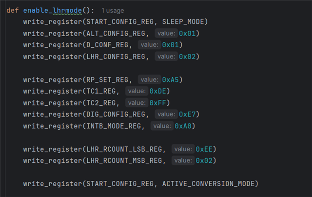
    I'm already familiar with the different registers of the LDC1101, but I'm still unsure about which specific configurations are required to properly activate LHR mode. Based on the values shown in your screenshots, are those settings intended to enable LHR mode? I’ve tried replicating them, but I still get zero values in both the L_DATA and LHR_DATA registers. One thing I noticed is that after writing those values, my STATUS register shows 0x7C. Do you know what this might indicate?

    To give you a better idea of how I’m setting up LHR mode, I’ve attached a screenshot of my code, showing the specific register values I’m writing. Also, while working in RP+L mode, I noticed that I’m getting valid RP readings, but the L_DATA seems to remain constant. Is that expected behavior? I find it a bit strange and would appreciate your insights.

    Thanks again.

  • Joseph,

    Thank you for the feedback. I will try to reproduce what you are seeing with our EVM & GUI and will update this thread by COB on Thursday.

    Regards,
    John

  • Hi John,

    Thanks for the update. I’ll be looking forward to your findings.

    What’s most confusing is that I’m getting Rp data in RP+L mode, but not L data. After noticing the L values were constant despite putting materials near the sensor, I tried a quick continuity test while the sensor was open (I know this isn’t ideal), which led me to disturb the PWM pin (CLKIN) on the MIKROE-3240. I noticed that moving the pin caused the L values to change briefly, but they still stayed constant and didn’t seem meaningful. This makes me suspect the issue might be related to the Raspberry Pi’s clock configuration or compatibility with the CLKIN input. I am using the pigpio library to the Pin 12 of the device to generate a 16 MHz PWM signal with 50% duty cycle.

    If that’s not the case, I might be missing a specific register configuration. And if that’s also ruled out, since I’ve already verified that SPI communication isn’t the problem, it’s possible that the click board or the LDC1101 chip itself is faulty.

    Appreciate your help!

  • Hi John,

    If we can’t get reliable inductance data working, we’re planning to proceed using only the RP data. Would measuring RP alone be enough to classify metals like copper, aluminum, and steel?

    Our goal is to estimate the resistivity or conductivity of a sample. The plan is to collect RP data and apply regression to relate it to resistivity. Do you think this approach is feasible?

    Also, since our metal targets will vary in size and shape, we’re considering normalizing the measured area with the RP value to improve model accuracy. Do you think this would help? Any suggestions for improving our strategy are very welcome.

    Thanks again for your support!

  • Joseph,

    From the register info you shared, it looks like the START_CONFIG register is set to SLEEP_MODE.
    It should be set to Active Conversion mode (0x00).

    The ALT_CONFIG register setting (0x01) is for LHR and L-only measurements. Any Rp measurements are invalid.
    Rp data from this mode is unlikely to be useful. 

    Please see if changing the START_CONFIG register fixes the problem.

    Also, please review the data sheet descriptions of the various registers and be sure their values correspond to the measuring conditions you want to use.

    regards,
    John