This thread has been locked.

If you have a related question, please click the "Ask a related question" button in the top right corner. The newly created question will be automatically linked to this question.

TMCS1101: TMCS1101A4B Dropouts after switching relays

Part Number: TMCS1101
Other Parts Discussed in Thread: TPL9201

Tool/software:

Hello,

I'm having an issue with the TMCS1101A4B and kindly ask for help.

I power on a 230V 0.5A motor by switching on a relay and then measure the current with the TMCS1101.

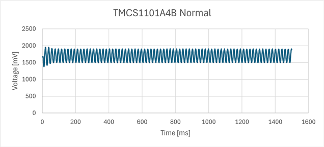
Immediately after switching the relay, I often observe a dropout of the TMCS1101 for a short or longer period; see the attached images.
The VOUT just drops to 0V and automatically returns after this period.

Can anybody explain this behaviour or does anybody have an idea what's causing this? I have no other issues and everything else is working fine.

Thanks!

  • Hi Peter,

    Can you please provide a scope shot of the supply voltage during these dropout periods? 

    Please ensure that when you are probing you connect to the ground of the device, and use a probe with a short ground connection as shown here.

    Thanks,

    Holly

  • Hi Holly,

    I've tried to measure it with the probe connections as short as possible directly at the pins of the TMCS1101.

    See following pictures of a short dropout. I've zoomed in to see the start of the drop. Yellow signal is 5V VS and green is VOUT.

    Thank you.

  • Hi Peter,

    There is a lot of noise on the supply which could be causing these issues. Can you please show me the layout of the bypass capacitor you have on the supply?

    BR,

    Holly

  • Hi Holly,

    see attached schematic/layout. I didn't create the layout and I'm just trying to analyse it myself to fix the issue.

    This is what I found out so far regarding the capacitors:
    The 5V is generated by a TPL9201, runs through a MIC94092 on/off switch and then to 8 of the TMCS1101.
    There is one 100nF at the MIC94092 and one at each TMCS1101.
    I don't see any other capacitors on the 5V line.

    For testing I soldered a 10uF in parallel to the 100nF of the TMCS1101 where I'm measuring the dropouts.
    The noise and dropouts are still present even with the added 10uF.

    I see that the 5V line runs underneath the TMCS1101. Can this be a problem?

    Thank you.

  • Hi Peter,

    The 5V line under the TMCS1101 can be a problem if there is a large amount of current running through it. However, if the current is small this should not pose much of an issue.

    On the schematic and layout you sent me the capacitor labels do not align. I assume C4 in the layout correlates to C2 in the schematic?

    I am unfamiliar with this layout tool; is the trace circled above connected to GND? I do not see a via nor can I tell where this trace is going.

    It might be worth looking into adding a ferrite bead on the supply line to clean up the noise on VS. 

    Please let me know about the capacitor I showed and we can then see if the ferrite bead will be necessary.

    Best,

    Holly

  • Hi Holly,

    yes C4 equals C2, it was just from another of the 8 identically TMCS1101.

    The motor connected for testing uses about 0.5 A.

    The trace you circled is connected to GND.

    I also found a ferrite bead on the 5V line at the output of the MIC94092; see attached schematic.

    Thanks!

  • Hi Peter,

    Layout of this ferrite is very important to reduce the noise. The ferrite you have shown needs to be placed as close to the supply pin as possible. Any length of trace between the ferrite and the supply pin acts as an antenna for the noise.

    With the ferrite you have chosen on supply it is also important that you have a ferrite connected between the cap and GND. (the circled portion in the previous image.

    These changes should reduce the noise on the supply voltage and therefore stop the dropout.

    Best,

    Holly

  • Hi Holly,

    just two questions to verify that I've understood you correctly:
    The ferrite L9 should be moved close to the VS pin of the TMCS1101 and an additional ferrite should be placed between the cap C4 and GND also close to the VS pin of the TMCS1101?
    I assume that this is for each of the 8 TMCS1101, so I need 16 ferrites in total?

    Thank you very much for your help!

  • Peter,

    If the TMCS1101s are close together you can probably get away with one filter for the devices. 

    I would recommend no more than 2 devices per filter. You could place the ferrites for these two devices in the spot circled green.

    The ferrite L9 should be moved close to the VS pin of the TMCS1101 and an additional ferrite should be placed between the cap C4 and GND also close to the VS pin of the TMCS1101?

    Yes.

    BR,

    Holly

  • Hi Holly,

    the GND pin of the TMCS1101 and the circled GND of C4 are currently connected through a GND layer (See "Original" in the following image).

    If I just add the ferrites this would result in "Var. A". But according to your schematic it should be "Var. B" right?

    Thank you again.

  • Peter,

    This is correct. Ideally, you want the routing to be as it is in Var B. 

    Best,

    Holly