This thread has been locked.

If you have a related question, please click the "Ask a related question" button in the top right corner. The newly created question will be automatically linked to this question.

AWR1843: CAN-FD not working on custom PCB

Part Number: AWR1843


Tool/software:

Hi,

We have designed a custom PCB based on AWR1843BOOST. We are using Medium Range Radar (MRR) example, which outputs data on both UART and CAN-FD by default.

I compiled and uploaded the same .bin on both EVM (AWR1843BOOST) and our custom PCB:

- Both EVM and custom PCB have UART data output. (MRR_Visualizer working)

- Have CAN output on EVM but not on the custom PCB.


Tests:

- I suspected BGA pins are not connected, removed R4 and R7 (0ohm jumpers): both pins have 3.3V on AWR1843 side, so it is connected.

- I checked if software gives any errors inside “Can_Initialize()” function, it is not.

- I checked CAN-FD lines on empty PCB, there is no problem.

- TODO: will be trying prebuilt binaries from previous radar_toolbox versions.


Details:

- Same pins used as EVM: D13 (CAN-FD_RX) and E14 (CAN-FD_TX)

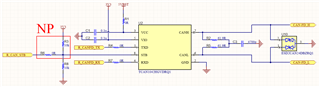
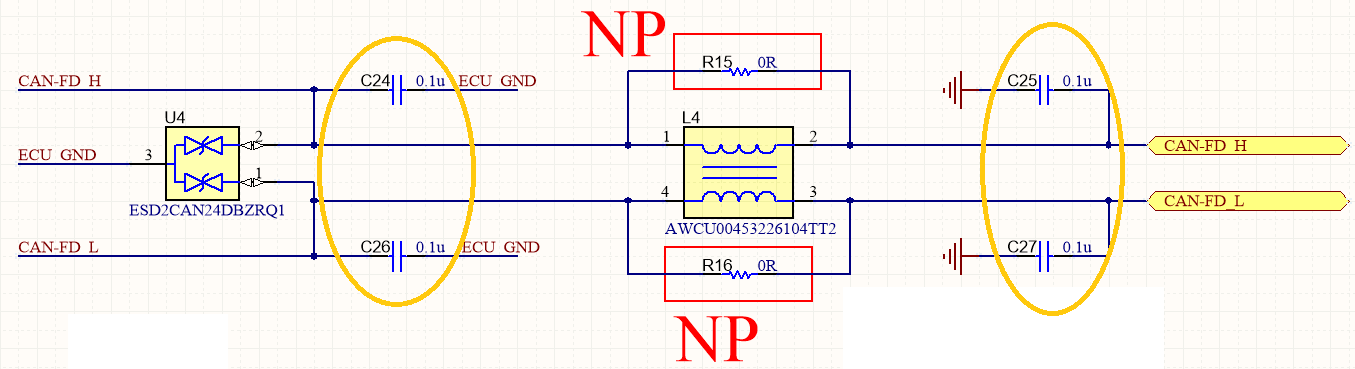
- Only difference to EVM, we dont use mux (TS3A5018RSVR) between AWR1843 to can transceiver (TCAN1042HGVDRQ1).

- [CCS Version: 12.8.1.00005] [SDK Version: mmwave_sdk_03_06_02_00-LTS] [Radar Toolbox Version: radar_toolbox_3_00_00_05]

- IC details on EVM and custom PCB. (EVM:19ZC8P9 Custom:32ZC309)

Custom PCB:

  • Hello,

    Allow me to get back to you on this request,

    -E. Shareef

  • + UPDATE

    I tried to change CAN-FD pins on EVM as follows:

    - CAN-FD_TX : E14 -> P10
    - CAN-FD_RX : D13 -> N10

    This is also not working for both EVM and custom PCB.

    ...
        gTxDoneFlag = 0;
        gRxDoneFlag = 0;
    
        /* Setup the PINMUX to bring out the XWR16xx CAN pins */
    #if 0
        Pinmux_Set_OverrideCtrl(SOC_XWR18XX_PINE14_PADAE, PINMUX_OUTEN_RETAIN_HW_CTRL, PINMUX_INPEN_RETAIN_HW_CTRL);
        Pinmux_Set_FuncSel(SOC_XWR18XX_PINE14_PADAE, SOC_XWR18XX_PINE14_PADAE_CANFD_TX);
    
        Pinmux_Set_OverrideCtrl(SOC_XWR18XX_PIND13_PADAD, PINMUX_OUTEN_RETAIN_HW_CTRL, PINMUX_INPEN_RETAIN_HW_CTRL);
        Pinmux_Set_FuncSel(SOC_XWR18XX_PIND13_PADAD, SOC_XWR18XX_PIND13_PADAD_CANFD_RX);
    #else   //NOT WORKING? is it not enough to use other pins for can-fd
        Pinmux_Set_OverrideCtrl(SOC_XWR18XX_PINP10_PADAU, PINMUX_OUTEN_RETAIN_HW_CTRL, PINMUX_INPEN_RETAIN_HW_CTRL);
        Pinmux_Set_FuncSel(SOC_XWR18XX_PINP10_PADAU, SOC_XWR18XX_PINP10_PADAU_CANFD_TX);
    
        Pinmux_Set_OverrideCtrl(SOC_XWR18XX_PINN10_PADAV, PINMUX_OUTEN_RETAIN_HW_CTRL, PINMUX_INPEN_RETAIN_HW_CTRL);
        Pinmux_Set_FuncSel(SOC_XWR18XX_PINN10_PADAV, SOC_XWR18XX_PINN10_PADAV_CANFD_RX);
    #endif
    
        /* Configure the divide value for MCAN source clock */
        SOC_setPeripheralClock(gMrrMSSMCB.socHandle, SOC_MODULE_MCAN, SOC_CLKSOURCE_VCLK, 4U, &errCode);
    
        /* Initialize peripheral memory */
        SOC_initPeripheralRam(gMrrMSSMCB.socHandle, SOC_MODULE_MCAN, &errCode);
        
        /* these functions are not needed according to:
         * https://e2e.ti.com/support/sensors-group/sensors/f/sensors-forum/1078531/awr1843aopevm-can-output-examples/3992954?tisearch=e2e-sitesearch&keymatch=awr1843%2525252520CSL_FINSR#3992954
         * https://e2e.ti.com/support/sensors-group/sensors/f/sensors-forum/1029284/awr6843aop-question-about-adding-canfd-mcan
        CSL_FINSR(0x43201450, 22, 22, 0x1U);
        CSL_FINSR(0x4320140C, 26, 16, 0x23U);
        */
    ...

  • + UPDATE

    - I tried prebuilt binaries for MRR from previous versions of radar toolbox, still not working (1_30_01_03 / 2_30_00_12 / 3_00_00_05).

    - I tried to control E14 and D13 pins on custom PCB as GPIO, able to prive both pins high and low.

    + Is it possible that CAN-FD problem is about the software not working on the custom PCB which has newer AWR1843?

    (EVM:19ZC8P9 [2021 Sep?] | Custom:32ZC309 [2023 Feb?])

    static void MRR_MSS_initTask(UArg arg0, UArg arg1)
    {
    ...
        /* Initialize the GPIO */
        GPIO_init();
    
        Pinmux_Set_OverrideCtrl(SOC_XWR18XX_PINE14_PADAE, PINMUX_OUTEN_RETAIN_HW_CTRL, PINMUX_INPEN_RETAIN_HW_CTRL);
        Pinmux_Set_FuncSel(SOC_XWR18XX_PINE14_PADAE, SOC_XWR18XX_PINE14_PADAE_GPIO_20);
        Pinmux_Set_OverrideCtrl(SOC_XWR18XX_PIND13_PADAD, PINMUX_OUTEN_RETAIN_HW_CTRL, PINMUX_INPEN_RETAIN_HW_CTRL);
        Pinmux_Set_FuncSel(SOC_XWR18XX_PIND13_PADAD, SOC_XWR18XX_PIND13_PADAD_GPIO_19);
    
        GPIO_setConfig(SOC_XWR18XX_GPIO_20, GPIO_CFG_OUTPUT);
        GPIO_setConfig(SOC_XWR18XX_GPIO_19, GPIO_CFG_OUTPUT);
    
        GPIO_write(SOC_XWR18XX_GPIO_20, 1); // E14
        GPIO_write(SOC_XWR18XX_GPIO_19, 0); // D13
    ...

  • Hello,

    I am reviewing the schematic, apologies this is taking longer 

    -E. Shareef

  • Hello,

    There shouldnt be any issues bypassing the MUX to connect directly to TCAN.

    However, there might need to be a software update for this Mux bypass. Referring you to software team.

    -E. Shareef

  • Hello,

    Turns out these capacitors (just before the output connector) were causing this problem, removing them solved the issue.

    In another project we were using this circuit, but for some reason, AWR1843 (or TCAN1042) stops the communication and keeps CAN-FD lines HIGH when they are mounted.

    Thank you for your attention.