This thread has been locked.

If you have a related question, please click the "Ask a related question" button in the top right corner. The newly created question will be automatically linked to this question.

MMWCAS-RF-EVM: Using MMWCAS-RF-EWM for SAR-Imaging in combination with a conveyor belt

Part Number: MMWCAS-RF-EVM

Tool/software:

Hi there, 
We would like to use the MMWCAS-RF EWM mounted on an MMWCAS-RF-DSP board in a SAR process to generate an image. For image reconstruction, a Range Migration Algorithm with phase compensation is used. The radar board is mounted in a tunnel, which is lined with absorbent mats on the inside to reduce environmental scatter. The following pictures schematically show the setup we used. 

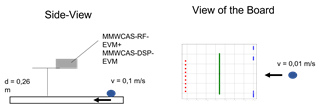
The radar board is 0.26 meters away from the target object. The object moves relative to the radar board at a speed of 0.1 m/s on a conveyor belt, perpendicular to the azimuth alignment of the board. The "Inter_Frame_Interval" has been set to 0.01 s in the LUA script. Other parameters used are Start_freq = 77 GHz, Slope = 70.295 MHz, idle_time = 7 us, adc_start_time = 4 us, adc_samples = 256, sample_freq =  5020 ksps, ramp_end_time = 55, rx_gain = 30, start_chirp_tx = 0, end_chirp_tx = 11, nchirp_loops = 4, n_frames = 250.  

For evaluation, the first block from each frame is used so that the measurement point intervals are equidistant, each being 0.001 m. The virtual antennas are equidistant with lambda/4. 

The following images were generated at different distances for focusing the target object. 


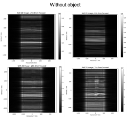
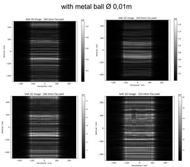
Do you have any idea why we observe a form of aliasing in the vertical direction, both with and without the object? For calibration, we use the same computational procedures as those found in C:\ti\mmwave_studio_02_01_01_00\mmWaveStudio\MatlabExamples. Could a re-recording of data for calibration improve the result? 
I found another script online. The authors also used a matrice called “delay offset” for every virtual channel they used to calibrate the beat frequency offset. Is there any Example how to obtain these offset times? 


Kind regards, 

Robin 

  • Hi,

    Our support team is not familiar with this use case. We have to let this question open for other forum members to respond.

    thank you

    Cesar

  • Hello Robin.

    Thank you for the question. Everything looks OK in terms of chirp config and horizontal scanning (1mm inter-sampling distance).

    I want to confirm a few things along the vertical axis:

    - There should be some overlapping antennas across vertical domain. Have you handled this in your algorithm? You need to create a uniform virtual array with no overlapping antennas for the range-migration algorithm.

    - Since the vertical aperture size is large compared to the target distance, the monostatic RMA will not work directly. You need either a multistatic algorithm (back-propagation, etc.) or a multistatic-to-monostatic conversion before RMA. You can refer to the algorithms at the following link: www.mathworks.com/.../78381-mimo-sar-mmwave-imaging-toolbox

    Regards.

    Muhammet

  • Hello Muhammed,

    Thank you for your reply.
    We are processing 86 virtual channels in the vertical direction, which are equidistant from each other. The distance is λ/4.

    Apologies, I forgot to mention that before applying the Range-Migration Algorithm, we perform a Multistatic-to-Monostatic conversion, as is also found in the Matlab Toolbox.

    Currently, we are calibrating the data with a calibration intended for standard TDM MIMO calculations. In the Matlab Toolbox, the data is calibrated with simulated data. Is it necessary to use the simulated data?

    Regards,
    Robin