


Other Parts Discussed in Thread: AWR2243, MMWCAS-RF-EVM,
Tool/software:
Hello everyone,
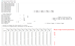
We are trying to implement a SAR algorithm using the MMWCAS-RF-EVM and MMWCAS-DSP-EVM boards (Device: AWR2243) in cascade configuration using Python. In order to select equidistant virtual channels in azimuth we implemented an algorithm that returned the antenna specification seen in the image. The chirping and chirp schedule configuration of the boards was done using the file "Cascade_Configuration_MIMO.lua" in mmWaveStudio 2.1.1.0. (ti\mmwave_studio_02_01_01_00\mmWaveStudio\Scripts\Cascade). The measurement is done with the file "Cascade Capture" where the frames and the number of chirp loops where adapted (nframes_master, nframes_loop set to 249 and nchirp_loops to 4; adc_samples remaining 256 and all 12 chirps are used), so all receivers and transmitters were
used. If our interpretation is correct, the aforementioned chirp schedule triggers the TX antennas from left to right and then the last three TX antennas of the master chip from bottom left to top right (when facing the board; see images of antenna positions and excerpt of the lua file for configuration).

We found a description for the raw data formatting of the device 12xx for complex values in the document 'Mmwave Radar Device ADC Raw Data Capture' on p. 12 and in the pdf file 'mmWave Sensor Raw Data Capture Using the TSW1400 Board' on page 16 (see attached images) but we are not sure if this applies for the 2243 as well:


The MATLAB script 'read_ADC_bin_TD2_separateFiles.m"
(\ti\mmwave_studio_02_01_01_00\mmWaveStudio\MatlabExamples\4chip_cascade_MIMO_example\utils\dataParse) containes these lines:
adcData1 = adcData1(1:2:end) + sqrt(-1)*adcData1(2:2:end);
adcData1 Complex = reshape(adcData1, numRXPerDevice, numSamplePerChirp, numChirpPerLoop, numLoops);
adcData1Complex = permute(adcData1Complex, [2 4 1 3]);

This means that the entire file string is structured according to following scheme: First the receivers (4), then the samples (256), then the chirps (12), then the chirp loops (4), and finally, the frames (249).
In Python this would be analogously:
adc_data_reshaped = np.reshape(adc_data, [numRXPerDevice,
numSamplePerChirp,
numChirpPerLoop,
numLoops, order='F') # 'F': Row-major order
adc_data_reshaped = np.transpose(adc_data_reshaped, (1, 3, 0, 2))
If we do this and we plot all the samples of the block of the first receiver and the first chirp (adc_data_reshaped[:, 0, 0, 0]) we get the time series of the signal you see in the attachments. When we look at the signals using the mmwStudio post-processing function the signals look like the first quarter of this series, so we believe that there is a misinterpretation here.

Our questions are now:
1) Is the above configuration and interpretation valid/correct?
2) Assuming that this is the case: What is the exact raw data formatting for the MMWCAS-(RF, DSP)-EVM combo using the AWR 2243 device?
Thanks in advance
