This thread has been locked.

If you have a related question, please click the "Ask a related question" button in the top right corner. The newly created question will be automatically linked to this question.

IWR1843BOOST: IWR1843

Part Number: IWR1843BOOST
Other Parts Discussed in Thread: IWR1843

Tool/software:

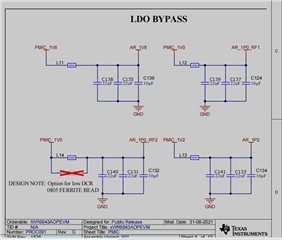
When I refer to TI's DEMO board to design the IWR1843 power supply, the 1.0V power supply track adopts the LC collocation in the figure below, and I found that IWR1843 frequent restarts in actual use, I think the voltage of 1.0v is too low, I increased the voltage output of the BUCK2 of the LP87524J to 1.2V, and still found that the IWR1843 restarts repeatedly, at this time, the voltage of the BGA pin near the IWR1843 is 970mv, which should not be restarted in theory. What causes the chip to reboot?
 
 When I replace the 1.0uH inductor with a bead, the IWR1843 is working normally, and the voltage measured near the IWR1843 is 916mv, and the voltage is still lower but it doesn't restart, I don't know why this happens?

  • Hello.

    We are looking into this; please provide us a few days to give a response.

    Sincerely,

    Santosh

  • Hi,

    What is the DCR of the ferrite bead or the inductor being used? The ferrite bead is used to prevent any supply noise. However, 916mV is out of the datasheet recommended specification of 950mV. I would recommend using low DCR ferrite bead. The frequent restarts in case of inductor could be caused by undershoot or overshoot.

    Regards

    Ankit

  • The DCR of the ferrite bead is 25mohm,The DCR of the inductor is 15mohm(We deliberately selected low DCR inductors).

     Inductance will naturally cause the voltage ripple to have a larger peak-to-peak value, and the 960 mV and 916 mV I mentioned are both the lowest measured values for the 1.0 V power rail.My question is, why doesn't it restart when the voltage is lower using ferrite beads compared to using inductors?I don't think it's the low voltage that's causing the radar to restart, but I don't know what else is causing it.Does the use of inductors cause other problems, such as poor loop phase margins?

  • Hi,

    What is the saturation current for the inductor? The 1V rail is high current carrying rail with peak current of 2A. The saturation current of the inductor should be at least 2-3 time of the peak current. Can you please confirm if the Isat is greater than 4A?

    Regards

    Ankit

  • Hi,

    This part seems to be alright. However, what is the reasoning behind using a 1uH part? I would recommend replacing with a 100nH part with Isat > 4A and see if the issue is resolved.

    Regards

    Ankit

  • When I use this inductor, the ripple of the power supply is composed of sine waves, and when I use beads, the ripple of the power supply is very messy.

  • Hi,

    Can you please share oscilloscope shot for the power supply waveforms? Is it ripple of the power supply when bead is used or the noise? I would still recommend replacing with a 100nH part with Isat > 4A and see if the issue is resolved.

    Regards

    Ankit