This thread has been locked.

If you have a related question, please click the "Ask a related question" button in the top right corner. The newly created question will be automatically linked to this question.

IWRL6432BOOST:Complex Data/ Phase Reconstruction

Part Number: IWRL6432BOOST
Other Parts Discussed in Thread: IWRL6432

Tool/software:

Hello TI Team,

I am currently working with the IWRL6432BOOST and the DCA1000 to capture raw ADC data. As I understand it, the DCA1000 only provides real (I-only) ADC samples, and does not output the quadrature (Q) component.

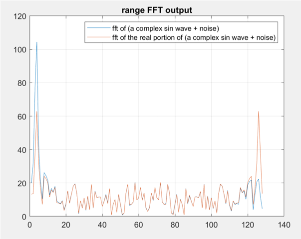
I know that performing a Range FFT is possible using only real-valued ADC samples.
However, my main question is:
How can Doppler and angle (AoA) estimation be performed without access to the Q data or explicit phase information?

Has the IWRL6432 an intern quadrature Filter? Or is the phase information computed and used internally, even though it is not available through the DCA1000?

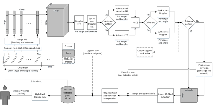
Furthermore, the out-of-box demo can output a point cloud over UART, which includes range, velocity, and angle information.
How is this calculated if only real ADC data is available?

My assumption is that TI internally reconstructs a complex signal representation (e.g., using a Hilbert transform or internal phase modeling) to enable this processing. Is that correct?

For custom processing in MATLAB or Python, would it be advisable to reconstruct a complex signal from the real ADC samples using a Hilbert transform, in order to perform Doppler and angle FFTs?

Thank you in advance for your support!

  • HI, there:

    Although the ADC data is real, the range FFT output is actually complex and has phase information.   On the other hand, since the range FFT input is real, the range FFT output is symmetric, we only use first half and ignore the second half (no new information there).

    Best,

    Zigang  

  • Hello Zigang,

    thank you for your reply.

    However, I feel that my original question was not fully answered.

    To clarify:

    I understand that the range FFT output is complex due to the real input being processed, and that only the first half is used due to symmetry.

    My main question is whether the phase information from the range FFT output is explicitly used for Doppler and Angle (AoA) estimation, given that only real ADC samples are available.

    In other words:

    Are the phase components generated after the first real range FFT sufficient for Doppler and Angle estimation?

    Or is there any internal quadrature generation (e.g., quadrature mixing or Hilbert transform) before or during the range FFT inside the IWRL6432 that I should be aware of?

    Thank you very much for your further clarification!

  • Hi, Tom:

    We do not apply any Hilbert transform before taking FFT.  The complex value out of range FFT is sufficient for Doppler and Angle estimation.   

    I did a simple experiment as below.  It shows the real-signal has a potential 3dB lower SNR compare to the complex chain.  You can do something similar on your side to check the phase value. 

    Best,

    Zigang

  • So, if I understand correctly, no BPM phase estimation is performed for angle estimation either? Only the FFT data is used?

  • Hi, Tom:

    Range FFT is applied to each antenna.  If you used BPM instead of TDM, then we need to apply BPM demodulation between every two chirps before angle estimation.   This portion is the same between real ADC or complex ADC structure. 

    Best,

    Zigang

  • So is the following process chain right? RAW ADC Data → Windowing → Range FFT → Doppler FFT → Angle FFT

  • Hello,

    That is correct yes. This is a diagram of our processing chain for IWRL6432 Motion and Presence demo. Windowing occurs before range fft but we do extra steps such as clutter removal (zero doppler removal)

    Best Regards,

    Pedrhom

  • Hi, Tom:

    We can run out of memory if we do range FFT, Doppler FFT, azimuth angle FFT and elevation angle FFT, and saved all 4D FFT output. 

    The traditional approach is as below:

    1) Range FFT -> Doppler FFT -> non-coherent combine cross antenna -> range-doppler heatmap 

    2) Apply peak detection (for example CFAR) on range-Doppler heatmap.

    3) After that, we do angle FFT for each detected peak to get angle information for each peak. 

    Other range-angle heatmap can also be used, refer to Pedrhom's reply.

    Best,

    Zigang