


Other Parts Discussed in Thread: AWR2944
Tool/software:
Hi ,
We use OOB demo with TDM config, per below document and radar config, some question want to clarify
./ti/mmwave_mcuplus_sdk_04_04_01_02/mmwave_mcuplus_sdk_04_04_01_02/ti/datapath/dpu/rangeproc/docs/doxygen/html/dpu_rangehwa.html
Radar config:
sensorStop
flushCfg
dfeDataOutputMode 1
channelCfg 15 15 0
adcCfg 2 0
adcbufCfg -1 1 1 1 1
lowPower 0 0
profileCfg 0 77 186 7 57.14 0 0 70 1 656 13349 0 0 30
chirpCfg 0 0 0 0 0 0 0 1
chirpCfg 1 1 0 0 0 0 0 4
chirpCfg 2 2 0 0 0 0 0 8
chirpCfg 3 3 0 0 0 0 0 2
frameCfg 0 3 16 0 656 100 1 0
1. From OOB source codes and radar config, it should be below setting.
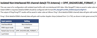
2. Is the radar Cube is as below?
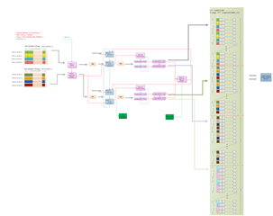
3. If we output Radar Cube with UART, how can we verify the data order is the same as the layout as above picture?
typedef struct DPIF_RadarCube_t
{
/*! @brief Radar Cube data Format @ref DPIF_RADARCUBE_FORMAT */
uint32_t datafmt;
/*! @brief Radar Cube buffer size in bytes */
uint32_t dataSize;
/*! @brief Radar Cube data pointer
User could remap this to specific typedef using
information in @ref DPIF_RADARCUBE_FORMAT */
void *data;
}DPIF_RadarCube;
4. We'd like to get Radar Cube and compute detection matrix by ourself.
Thanks
BRs
Bruce
