This thread has been locked.

If you have a related question, please click the "Ask a related question" button in the top right corner. The newly created question will be automatically linked to this question.

IWRL6432AOP: Help with radar chip layout.

Part Number: IWRL6432AOP

Tool/software:

Hello,

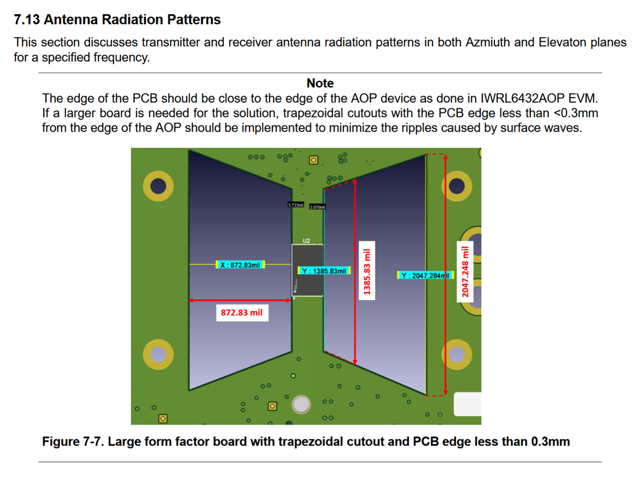
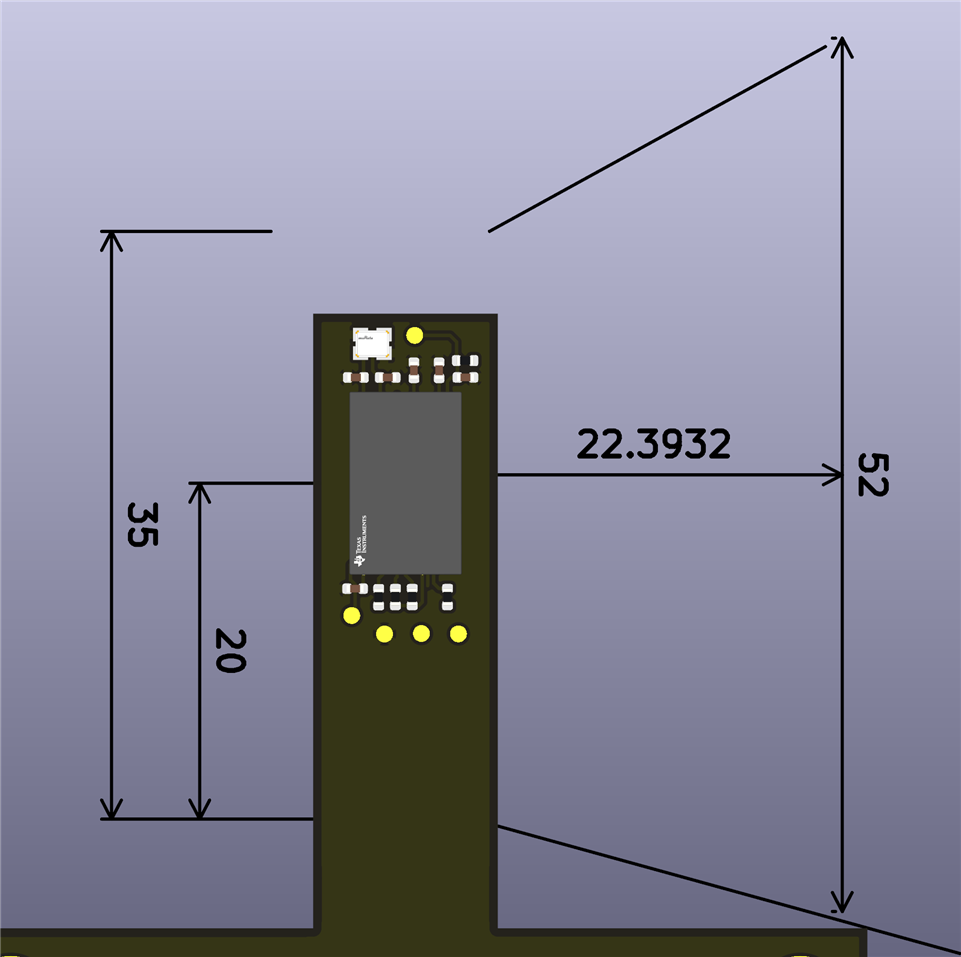
I'm working on a board that uses the IWRL6432AOP radar chip, but I'm a bit unsure about the layout.

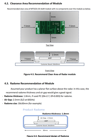
The datasheet recommends this but that makes the PCB really big and cumbersome. The  IWRL6432AOPEVM don't really adhere to these guidelines either and there is another module that only needs a spacing of around 5mm on all sides so I'm not entirely sure what to do now. Ideally I would place the chip in the middle of the PCB but I'm not sure if this interferes with the radar waves too much. Thanks for the help!TI datasheetJorjin module datasheet My design

  • Emiel, 

    The cutouts and and board shape recomendations are to ensure that there are no PCB re-radiations that could induce ripple in the radiation patterns (constructive and destructive interference). This could reduce your SNR and cause poor off-boresight performance. I strongly recomend following TI's recomendation for layouts. We are not responsible for 3P design or materials.

    If you are unable to follow the cutout or board sizing restructions, you could investigate carbon-loaded absorbers as an alternative to the cut-outs. However, absorbers in this case have not be validated by our team. If you do want to try the absorbers, please ensure you source absorbers tuned to 60 GHz and please ensure that it is not a ferric absorber as the ferrite could impact the antenna radiation pattern. 

    Thanks! 

    Blake

  • Hi Blake,

    Thank you for your reply! Using absorbers sounds like a very interesting idea. I think I'll make two versions (if I can even finish the project on time Grimacing)

    If I managed to finish the project I'll post my findings here so other people have an answer too.

  • Best of luck with your project Emiel!