Tool/software:
Hi there!
We have designed a custom board with the AWR1843AOP, but it doesn’t work.
We used the AWR1843AOPEVM as a reference design.
We have done a lot of debugging, without any success.
The board consumes 100 mA in either functional or programming mode when we connect it to the 5V supply.
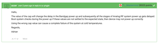
Here is the voltage sequence:
After searching the forum for a while, I realized we must see 0.9V on VBGAP pin, and we see it:
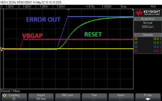
SOP pins are in flashing mode, Here is the SOP2 and reset pin voltages after applying power:
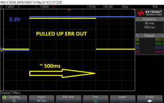
ERROR IN and ERROR OUT are pulled up to 3.3V.
WARM RESET also pulled up to 3.3V.
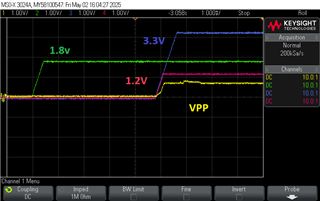
Now we see this startup sequence on these pins: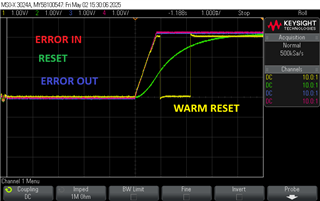
Also, after around 500ms, we see the ERROR OUTPUT pin goes low:
We can see a voltage around 500mV on CLKM pin, but it drops a little bit quickly, and we don't see any clock voltage on the CLKP pin: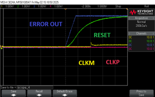
Looks like the radar never boots up. We don't see any oscillation at the crystal pins, and we are not sure where the problem is.
I have tried 4.7pF and 10pF capacitors (as our board has 6 layers, less layers compared to the TI reference design), but it didn't help.
Thank you for your help in advance.