This thread has been locked.

If you have a related question, please click the "Ask a related question" button in the top right corner. The newly created question will be automatically linked to this question.

MMWCAS-RF-EVM: AWR2243 Setting up DDMA via ar1.AdvChirpConfig_mult()

Part Number: MMWCAS-RF-EVM
Other Parts Discussed in Thread: AWR2243, , TDA2

Tool/software:

Hi everyone,

I am currently setting up the MMWCAS-RF-EVM board, my version has four AWR2243 chips. I was able to confirm that the board and the TDA2xx capture card works fine by validating it via the provided TDMA MIMO example.

My goal is to configure the board in a DDMA mode using an additional empty subband as described in e.g.: C:\ti\mmwave_mcuplus_sdk_04_07_00_01\mmwave_mcuplus_sdk_04_07_00_01\ti\datapath\dpc\objectdetection\objdethwaDDMA\docs\doxygen\html


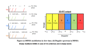
For the MMWCAS-RF-EVM board with 12 TX and 16 RX I will be using 13 subbands, 12 for the 12 TX and one extra subband.
I re-purposed the Cascade_Configuration_MIMO.lua script and replaced the chrirp configuration function by using  ar1.AdvChirpConfig_mult().
Further, I am using the ar1.AdvanceFrameConfig_mult() so that a single subframe with one chirp is looped.

This is my lua script:


--[[
Sequence being followed

A. CONFIGURATION
1. Connecting to TDA
1. Configuring Master from SOP till Channel Config
2. Configuring Slave (i) sequentially from SOP till SPI Connect. i = 1, 2, 3
3. Configuring Slaves together from F/W download till Channel Config
4. Configuring all devices together from LDO Bypass till Frame Config

NOTE:
Update the following in the script accordingly before running
1. metaImage F/W path on line 32
2. TDA Host Board IP Address on line 39
--]]
   
----------------------------------------User Constants--------------------------------------------
       
dev_list          =    {1, 2, 4, 8}       -- Device map
RadarDevice       =    {1, 1, 1, 1}       -- {dev1, dev2, dev3, dev4}, 1: Enable, 0: Disable
cascade_mode_list =    {1, 2, 2, 2}       -- 0: Single chip, 1: Master, 2: Slave

-- F/W Download Path

-- Uncomment the next line if you wish to pop-up a dialog box to select the firmware image file
-- Otherwise, hardcode the path to the firmware metaimage below
-- By default, the firmware filename is: xwr22xx_metaImage.bin

-- metaImagePath  =   RSTD.BrowseForFile(RSTD.GetSettingsPath(), "bin", "Browse to .bin file")
-- For 2243 ES1.1 devices
metaImagePath            =   "C:\\ti\\mmwave_dfp_02_02_02_01\\firmware\\xwr22xx_metaImage.bin"
-- For 2243 ES1.0 devices
-- metaImagePath            =   "C:\\ti\\mmwave_dfp_02_02_00_02\\firmware\\xwr22xx_metaImage.bin"

-- IP Address for the TDA2 Host Board
-- Change this accordingly for your setup

TDA_IPAddress     =   "192.168.33.180"

-- Device map of all the devices to be enabled by TDA
-- 1 - master ; 2- slave1 ; 4 - slave2 ; 8 - slave3

deviceMapOverall  =   RadarDevice[1] + (RadarDevice[2]*2) + (RadarDevice[3]*4) + (RadarDevice[4]*8)
deviceMapSlaves   =   (RadarDevice[2]*2) + (RadarDevice[3]*4) + (RadarDevice[4]*8)

-- Enable/Disable Test Source
-- This is useful during bringup

test_source_enable  =   0      -- 0: Disable, 1: Enable
   
------------------------------------------- Sensor Configuration ------------------------------------------------
--[[
The sensor configuration consists of 3 sections:
1) Profile Configuration (common to all 4 AWR devices)
2) Chirp Configuration (unique for each AWR device - mainly because TXs to use are
                        different for each chirp)
3) Frame Configuration (common to all 4 AWR devices, except for the trigger mode for the master)
Change the values below as needed. --]]

-- Profile configuration
local profile_indx              =   0
local start_freq                =   77     -- GHz
local slope                     =   79     -- MHz/us
local idle_time                 =   5      -- us
local adc_start_time            =   6      -- us
local adc_samples               =   256    -- Number of samples per chirp
local sample_freq               =   8000   -- ksps
local ramp_end_time             =   40     -- us
local rx_gain                   =   48     -- dB
local tx0OutPowerBackoffCode    =   0
local tx1OutPowerBackoffCode    =   0
local tx2OutPowerBackoffCode    =   0
local tx0PhaseShifter           =   0
local tx1PhaseShifter           =   0
local tx2PhaseShifter           =   0
local txStartTimeUSec           =   0
local hpfCornerFreq1            =   0      -- 0: 175KHz, 1: 235KHz, 2: 350KHz, 3: 700KHz
local hpfCornerFreq2            =   0      -- 0: 350KHz, 1: 700KHz, 2: 1.4MHz, 3: 2.8MHz

-- Frame configuration    
local start_chirp_tx            =   0
local end_chirp_tx              =   0
local nchirp_loops              =   160     -- Number of chirps per frame
local nframes_master            =   2     -- Number of Frames for Master
local nframes_slave             =   2     -- Number of Frames for Slaves
local Inter_Frame_Interval      =   100    -- ms
local trigger_delay             =   0      -- us
local trig_list                 =   {1,2,2,2} -- 1: Software trigger, 2: Hardware trigger    


------------------------------ API Configuration ------------------------------------------------
   
-- 1. Connection to TDA. 2. Selecting Cascade/Single Chip.  3. Selecting 2-chip/4-chip

WriteToLog("Setting up Studio for Cascade started..\n", "blue")

if(0 == ar1.ConnectTDA(TDA_IPAddress, 5001, deviceMapOverall)) then
    WriteToLog("ConnectTDA Successful\n", "green")
else
    WriteToLog("ConnectTDA Failed\n", "red")
    return -1
end

if(0 == ar1.selectCascadeMode(1)) then
    WriteToLog("selectCascadeMode Successful\n", "green")
else
    WriteToLog("selectCascadeMode Failed\n", "red")
    return -1
end

WriteToLog("Setting up Studio for Cascade ended..\n", "blue")
         
--Master Initialization

-- SOP Mode Configuration
if (0 == ar1.SOPControl_mult(1, 4)) then
    WriteToLog("Master : SOP Reset Successful\n", "green")
else
    WriteToLog("Master : SOP Reset Failed\n", "red")
    return -1
end

-- SPI Connect
if (0 == ar1.PowerOn_mult(1, 0, 1000, 0, 0)) then
    WriteToLog("Master : SPI Connection Successful\n", "green")
else
    WriteToLog("Master : SPI Connection Failed\n", "red")
    return -1
end

-- Firmware Download. (SOP 4 - MetaImage)
if (0 == ar1.DownloadBssFwOvSPI_mult(1, metaImagePath)) then
    WriteToLog("Master : FW Download Successful\n", "green")
else
    WriteToLog("Master : FW Download Failed\n", "red")
    return -1
end

-- RF Power Up
if (0 == ar1.RfEnable_mult(1)) then
    WriteToLog("Master : RF Power Up Successful\n", "green")
else
    WriteToLog("Master : RF Power Up Failed\n", "red")
    return -1
end            
         
-- Channel & ADC Configuration
if (0 == ar1.ChanNAdcConfig_mult(1,1,1,1,1,1,1,1,2,1,0,1)) then
    WriteToLog("Master : Channel & ADC Configuration Successful\n", "green")
else
    WriteToLog("Master : Channel & ADC Configuration Failed\n", "red")
    return -2
end
   
-- Slaves Initialization
   
for i=2,table.getn(RadarDevice) do
    local status    =    0                
    if ((RadarDevice[1]==1) and (RadarDevice[i]==1)) then
     
        -- SOP Mode Configuration
        if (0 == ar1.SOPControl_mult(dev_list[i], 4)) then
            WriteToLog("Device "..i.." : SOP Reset Successful\n", "green")
        else
            WriteToLog("Device "..i.." : SOP Reset Failed\n", "red")
            return -1
        end
               
        -- SPI Connect    
        if (0 == ar1.AddDevice(dev_list[i])) then
            WriteToLog("Device "..i.." : SPI Connection Successful\n", "green")
        else
            WriteToLog("Device "..i.." : SPI Connection Failed\n", "red")
            return -1
        end
           
    end
end  
   
-- Firmware Download. (SOP 4 - MetaImage)
if (0 == ar1.DownloadBssFwOvSPI_mult(deviceMapSlaves, metaImagePath)) then
    WriteToLog("Slaves : FW Download Successful\n", "green")
else
    WriteToLog("Slaves : FW Download Failed\n", "red")
    return -1
end
         
-- RF Power Up
if (0 == ar1.RfEnable_mult(deviceMapSlaves)) then
    WriteToLog("Slaves : RF Power Up Successful\n", "green")
else
    WriteToLog("Slaves : RF Power Up Failed\n", "red")
    return -1
end    

-- Channel & ADC Configuration
if (0 == ar1.ChanNAdcConfig_mult(deviceMapSlaves,1,1,1,1,1,1,1,2,1,0,2)) then
    WriteToLog("Slaves : Channel & ADC Configuration Successful\n", "green")
else
    WriteToLog("Slaves : Channel & ADC Configuration Failed\n", "red")
    return -2
end
           
-- All devices together        
         
-- Including this depends on the type of board being used.
-- LDO configuration
if (0 == ar1.RfLdoBypassConfig_mult(deviceMapOverall, 3)) then
    WriteToLog("LDO Bypass Successful\n", "green")
else
    WriteToLog("LDO Bypass failed\n", "red")
    return -2
end

-- Low Power Mode Configuration
if (0 == ar1.LPModConfig_mult(deviceMapOverall,0, 0)) then
    WriteToLog("Low Power Mode Configuration Successful\n", "green")
else
    WriteToLog("Low Power Mode Configuration failed\n", "red")
    return -2
end

-- Miscellaneous Control Configuration
if (0 == ar1.SetMiscConfig_mult(deviceMapOverall, 1, 1, 0, 0)) then
    WriteToLog("Misc Control Configuration Successful\n", "green")
else
    WriteToLog("Misc Control Configuration failed\n", "red")
    return -2
end

-- Edit this API to enable/disable the boot time calibration. Enabled by default.
-- RF Init Calibration Configuration
if (0 == ar1.RfInitCalibConfig_mult(deviceMapOverall, 1, 1, 1, 1, 1, 1, 1, 65537)) then
    WriteToLog("RF Init Calibration Successful\n", "green")
else
    WriteToLog("RF Init Calibration failed\n", "red")
    return -2
end
         
-- RF Init
if (0 == ar1.RfInit_mult(deviceMapOverall)) then
    WriteToLog("RF Init Successful\n", "green")
else
    WriteToLog("RF Init failed\n", "red")
    return -2
end

---------------------------Data Configuration----------------------------------
       
-- Data path Configuration
if (0 == ar1.DataPathConfig_mult(deviceMapOverall, 0, 1, 0)) then
    WriteToLog("Data Path Configuration Successful\n", "green")
else
    WriteToLog("Data Path Configuration failed\n", "red")
    return -3
end

-- Clock Configuration
if (0 == ar1.LvdsClkConfig_mult(deviceMapOverall, 1, 1)) then
    WriteToLog("Clock Configuration Successful\n", "green")
else
    WriteToLog("Clock Configuration failed\n", "red")
    return -3
end

-- CSI2 Configuration
if (0 == ar1.CSI2LaneConfig_mult(deviceMapOverall, 1, 0, 2, 0, 4, 0, 5, 0, 3, 0, 0)) then
    WriteToLog("CSI2 Configuration Successful\n", "green")
else
    WriteToLog("CSI2 Configuration failed\n", "red")
    return -3
end

---------------------------Sensor Configuration-------------------------


if (0 == ar1.ProfileConfig_mult(deviceMapOverall, 0, start_freq, idle_time, adc_start_time, ramp_end_time,
                                 0, 0, 0, 0, 0, 0, slope, 0, adc_samples, sample_freq, 0, 0, rx_gain)) then

    WriteToLog("Profile Configuration successful\n", "green")
else
    WriteToLog("Profile Configuration failed\n", "red")
    return -4
end

-- Chirp Configuration

for i=1,table.getn(RadarDevice) do    
    if ((RadarDevice[1]==1) and (RadarDevice[i]==1)) then
        ar1.AdvChirpConfig_mult(dev_list[i], 0, 1, 0, 0, 0, 0, 0, 0, 0, 0, 0, 1, 0, 0, 0, 0, 0)
        ar1.AdvChirpConfig_mult(dev_list[i], 1, 1, 1, 0, 0, 0, 0, 0, 0, 0, 0, 1, 0, 0, 0, 0, 0)
        ar1.AdvChirpConfig_mult(dev_list[i], 2, 1, 1, 0, 0, 0, 0, 0, 0, 0, 0, 1, 0, 0, 0, 0, 0)
        ar1.AdvChirpConfig_mult(dev_list[i], 3, 1, 1, 0, 0, 0, 0, 0, 0, 0, 0, 1, 0, 0, 0, 0, 0)
        ar1.AdvChirpConfig_mult(dev_list[i], 4, 1, 1, 0, 0, 0, 0, 0, 0, 0, 0, 1, 0, 0, 0, 0, 0)
        ar1.AdvChirpConfig_mult(dev_list[i], 5, 1, 0, 0, 0, 0, 0, 0, 0, 0, 4, 1, 0, 0, 0, 0, 0)
        ar1.AdvChirpConfig_mult(dev_list[i], 6, 1, 0, 0, 0, 0, 0, 0, 0, 0, 0, 1, 0, 0, 0, 0, 0)
   
        if (i==1) then
           ar1.AdvChirpConfig_mult(dev_list[i], 7, 1, 0, 1, 0, 0, 0, 0, 0, 0, 0, 1, 0, 0, 0, 0, 0)
           ar1.AdvChirpConfig_mult(dev_list[i], 8, 1, 0, 1, 5041, 0, 0, 0, 0, 0, 0, 1, 0, 0, 0, 0, 0)
           ar1.AdvChirpConfig_mult(dev_list[i], 9, 1, 0, 1, 10082, 0, 0, 0, 0, 0, 0, 1, 0, 0, 0, 0, 0)  
        elseif (i==2)  then
            ar1.AdvChirpConfig_mult(dev_list[i], 7, 1, 0, 1, 15123, 0, 0, 0, 0, 0, 0, 1, 0, 0, 0, 0, 0)
            ar1.AdvChirpConfig_mult(dev_list[i], 8, 1, 0, 1, 20164, 0, 0, 0, 0, 0, 0, 1, 0, 0, 0, 0, 0)
            ar1.AdvChirpConfig_mult(dev_list[i], 9, 1, 0, 1, 25205, 0, 0, 0, 0, 0, 0, 1, 0, 0, 0, 0, 0)  
           
        elseif (i==3)  then
            ar1.AdvChirpConfig_mult(dev_list[i], 7, 1, 0, 1, 30246, 0, 0, 0, 0, 0, 0, 1, 0, 0, 0, 0, 0)
            ar1.AdvChirpConfig_mult(dev_list[i], 8, 1, 0, 1, 35287, 0, 0, 0, 0, 0, 0, 1, 0, 0, 0, 0, 0)
            ar1.AdvChirpConfig_mult(dev_list[i], 9, 1, 0, 1, 40328, 0, 0, 0, 0, 0, 0, 1, 0, 0, 0, 0, 0)  
       
        elseif (i==4)  then
            ar1.AdvChirpConfig_mult(dev_list[i], 7, 1, 0, 1, 45369, 0, 0, 0, 0, 0, 0, 1, 0, 0, 0, 0, 0)
            ar1.AdvChirpConfig_mult(dev_list[i], 8, 1, 0, 1, 50410, 0, 0, 0, 0, 0, 0, 1, 0, 0, 0, 0, 0)
            ar1.AdvChirpConfig_mult(dev_list[i], 9, 1, 0, 1, 55451, 0, 0, 0, 0, 0, 0, 1, 0, 0, 0, 0, 0)  
        end
    end
end


ar1.ClearAdvChirpLUTConfig()
ar1.SetProfileAdvChirpConfigLUT(0, 4, 0, 0, 0, 0)
ar1.SetTxEnAdvChirpConfigLUT(4, 3, 7, 0, 0, 0)

for i=1,table.getn(RadarDevice) do    
    if ((RadarDevice[1]==1) and (RadarDevice[i]==1)) then
        ar1.AdvChirpLUTConfig_mult(dev_list[i], 0, 156)                
    end
end


-- Frame Configuration
-- Master
ar1.AdvanceFrameConfig_mult(1, 1, 0, 0, 0, 1, nchirp_loops, 10000000, 0, 1, 1, 10000000, 0, 0, 1, 128, 8000000,0, 1, 1, 8000000, 0, 0, 1, 128, 8000000, 0, 1, 1, 8000000, 0, 0, 1,128, 8000000, 0, 1, 1, 8000000, 2, 1, 0, 1, nchirp_loops, 512, 1, 128, 1, 1,128, 1, 1, 128, 1, 1)

-- Slaves
ar1.AdvanceFrameConfig_mult(2, 1, 0, 0, 0, 1, nchirp_loops, 10000000, 0, 1, 1, 10000000, 0, 0, 1, 128, 8000000,0, 1, 1, 8000000, 0, 0, 1, 128, 8000000, 0, 1, 1, 8000000, 0, 0, 1,128, 8000000, 0, 1, 1, 8000000, 2, 2, 0, 1, nchirp_loops, 512, 1, 128, 1, 1,128, 1, 1, 128, 1, 1)
ar1.AdvanceFrameConfig_mult(4, 1, 0, 0, 0, 1, nchirp_loops, 10000000, 0, 1, 1, 10000000, 0, 0, 1, 128, 8000000,0, 1, 1, 8000000, 0, 0, 1, 128, 8000000, 0, 1, 1, 8000000, 0, 0, 1,128, 8000000, 0, 1, 1, 8000000, 2, 2, 0, 1, nchirp_loops, 512, 1, 128, 1, 1,128, 1, 1, 128, 1, 1)
ar1.AdvanceFrameConfig_mult(8, 1, 0, 0, 0, 1, nchirp_loops, 10000000, 0, 1, 1, 10000000, 0, 0, 1, 128, 8000000,0, 1, 1, 8000000, 0, 0, 1, 128, 8000000, 0, 1, 1, 8000000, 0, 0, 1,128, 8000000, 0, 1, 1, 8000000, 2, 2, 0, 1, nchirp_loops, 512, 1, 128, 1, 1,128, 1, 1, 128, 1, 1)

ar1.SaveAdvChirpLUTConfig()


However after capturing and processing a frame I discovered, that the empyt subband is not empty.

Processing setup:

import os
import numpy as np
import matplotlib.pyplot as plt
chirps_per_frame = 160 # chirps/frame
adc_samples = 256 # adc sample
number_of_frames = 1 # number of frames
adcs_per_mmic = 4
raw_data = np.fromfile(os.path.join(path, "master_0000_data.bin"), dtype=np.int16, count=expected)
i_data = raw_data[::2]
q_data = raw_data[1::2]
complex = i_data + 1j * q_data
test_d = complex.reshape(chirps_per_frame, adc_samples, adcs_per_mmic)
test_d = test_d.transpose(1, 0, 2)

f1_td = np.fft.fft(test_d, axis=0)
f2_td = np.fft.fft(f1_td, axis=1)

The proccessing setup is based on the parsers provided in C:\ti\mmwave_studio_03_00_00_14\mmWaveStudio\MatlabExamples\4chip_cascade_MIMO_example\utils\dataParse

Also It seems that by default the first frame is always dropped. So that in order to capture one valid frame the lua script needs to configure the setup to capture two frames.

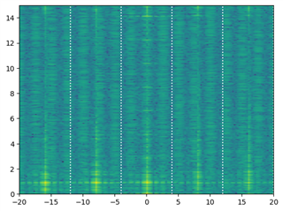
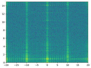
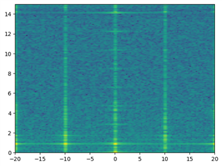
Range doppler map with corner reflector at ~1m and subbands:

plt.imshow(np.fft.fftshift(np.log(np.abs(f2_td[:,:, 0])), axes=( 1)), extent=[-20, 20, 0, 15,], aspect='auto', origin='lower')
for k in np.linspace(-13, 13, 13 + 1):
     plt.axvline(x=k * 20 / 13, ymin=0, ymax=15, linestyle=":", color="w")


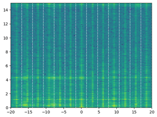
As can be seen appart from some refelction artifacts all subbands show the target at 1m range.

So my question is why am I observing this issue and where in my setup did I make a mistake? I suspect that there is an error in the Frame or Chirp config.

Thanks for your help.

Lorenz

  • Hi Lorenz, your query is being discussed with the experts. We will get back with some comments in a day's time. 

    Regards,
    Shailesh

  • Hi Lorenz, the configurations are looking OK. Can you try doing this with different number of bands and/or first with only one device enabled? This will help narrow down the scope a bit.

    Regards,

    Shailesh

  • Hi Shailesh

    sure here is the setup with only one device active (Master) and a DDMA configuration using 5 subbands:

    in the above provided Lua configuration script I made the following changes:

    RadarDevice       =    {1, 0, 0, 0}
    ...

    -- Do not RF Power Up Slave devices
    -- if (0 == ar1.RfEnable_mult(deviceMapSlaves)) then
    --     WriteToLog("Slaves : RF Power Up Successful\n", "green")
    -- else
    --     WriteToLog("Slaves : RF Power Up Failed\n", "red")
    --     return -1
    -- end    
    ...
    -- addapt chrip phase offest to use five subbands; 3 used 2 empty
    if (i==1) then
       ar1.AdvChirpConfig_mult(dev_list[i], 7, 1, 0, 1, 0, 0, 0, 0, 0, 0, 0, 1, 0, 0, 0, 0, 0)
       ar1.AdvChirpConfig_mult(dev_list[i], 8, 1, 0, 1, 13108, 0, 0, 0, 0, 0, 0, 1, 0, 0, 0, 0, 0)
       ar1.AdvChirpConfig_mult(dev_list[i], 9, 1, 0, 1, 26215, 0, 0, 0, 0, 0, 0, 1, 0, 0, 0, 0, 0)

    ...
    -- Ommit Frame config for Slaves
    -- ar1.AdvanceFrameConfig_mult(2, 1, 0, 0, 0, 1, nchirp_loops, 10000000, 0, 1, 1, 10000000, 0, 0, 1, 128, 8000000,0, 1, 1, 8000000, 0, 0, 1, 128, 8000000, 0, 1, 1, 8000000, 0, 0, 1,128, 8000000, 0, 1, 1, 8000000, 2, 2, 0, 1, nchirp_loops, 512, 1, 128, 1, 1,128, 1, 1, 128, 1, 1)
    -- ar1.AdvanceFrameConfig_mult(4, 1, 0, 0, 0, 1, nchirp_loops, 10000000, 0, 1, 1, 10000000, 0, 0, 1, 128, 8000000,0, 1, 1, 8000000, 0, 0, 1, 128, 8000000, 0, 1, 1, 8000000, 0, 0, 1,128, 8000000, 0, 1, 1, 8000000, 2, 2, 0, 1, nchirp_loops, 512, 1, 128, 1, 1,128, 1, 1, 128, 1, 1)
    -- ar1.AdvanceFrameConfig_mult(8, 1, 0, 0, 0, 1, nchirp_loops, 10000000, 0, 1, 1, 10000000, 0, 0, 1, 128, 8000000,0, 1, 1, 8000000, 0, 0, 1, 128, 8000000, 0, 1, 1, 8000000, 0, 0, 1,128, 8000000, 0, 1, 1, 8000000, 2, 2, 0, 1, nchirp_loops, 512, 1, 128, 1, 1,128, 1, 1, 128, 1, 1)

    Measurement setup is the same as before, a corner reflector at ~1m.

    The processing stays the same as previously. The range doppler map shows five subbands with five targets (peaks). Given This setup, I would expect only three targets in the first three subbands (counting from left) and two empty subbands.


    It would be really helpful for me if you could reproduce this setup / measurements and confirm the results.
    If you need the configuration script or any other material, please let me know, and I will send it to you.

    Thanks for your help.
    Lorenz

  • Hi Lorenz, can you try it out with 4 bands (1 empty) case? This will be quite close to what has been tried here. Also trying to understand if the signal duration not being a multiple of tone period is causing any significant leakage. Have you tried using any windowing functions before FFT? Also, what is the signal level difference at the 5 peaks, difficult to judge from the heatmap plot?

    Regards,

    Shailesh

  • Hi Shailesh

    Here is a plot of the same setup but with 4 subbands (1 empty)

    Without window function before FFT:

    f1_td = np.fft.fft(test_d, axis=0)
    f2_td = np.fft.fft(f1_td, axis=1)
    plt.imshow(np.fft.fftshift(np.log(np.abs(f2_td[:,:, 0])), axes=( 1)), extent=[-20, 20, 0, 15,], aspect='auto', origin='lower')

    With a hann window applied before the fft:

    hann_row = np.hanning(test_d.shape[0])
    hann_col = np.hanning(test_d.shape[1])

    # Create 2D Hann window by outer product
    hann_2d = np.outer(hann_row, hann_col)

    # Apply the 2D Hann window
    windowed_signal = test_d * hann_2d[:, :, np.newaxis]
    f1_td = np.fft.fft(windowed_signal, axis=0)
    f2_td = np.fft.fft(f1_td, axis=1)
    plt.imshow(np.fft.fftshift(np.log(np.abs(f2_td[:,:, 0])), axes=( 1)), extent=[-20, 20, 0, 15,], aspect='auto', origin='lower')


    Were you able to reproduce the beavior ? Do you need any resources from my side e.g. the configuration file etc.?

    Thanks for your help
    Lorenz

  • Hi Lorenz, 

    Can we have a better look at the final spectrum plots? Are these in log-scale? Can we know what are the peak-levels in each band? The empty band will usually not be completely empty and will have some leakage from other bands, so we should look for that case too. Can we compare the plots with a non-DDM case for that?

    Unfortunately, it will not be feasible for us to test this on an AWR2243 device in near future.

    Regards,

    Shailesh

  • Hi Lorenz, were you able to make any progress on this?

    Regards,

    Shailesh

  • Closing this inactive thread. Kindly post again if there is any update.