This thread has been locked.

If you have a related question, please click the "Ask a related question" button in the top right corner. The newly created question will be automatically linked to this question.

PGA970: The generated sine wave has poor quality with a small amplitude

Part Number: PGA970

Tool/software:

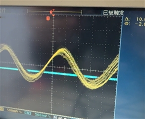
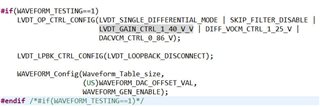
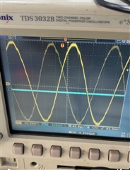
Hello, I designed and manufactured PCBs featuring PGA970 , I programmed and working perfectly using CCS version 9.3.0 and compiler V5.2.6. and I am using the default .gel file that came with the PGA970_Generic_1_6 firmware. But the generated sine wave has poor quality with a small amplitude of 400mV, appearing unclear, unstable, and exhibiting abrupt transitions. The waveform is shown below. 

My LVDT requires a 4Vpp sine wave. The waveform after tenfold amplification is shown below, 

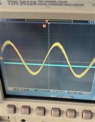
And the secondary output waveform of the LVDT is also provided. How can I generate a clear, stable sine wave with a peak-to-peak amplitude of 4V?

  • Hi Jin Jie, 

    When you programmed the waveform table in your firmware, how did you calculate the values for the lookup table? What is your desired frequency?

    To generate a sine wave of amplitude amp and frequency freq, calculate waveform table values using the formula: amp × sin(2πfreq × (0.5 μs + n1
    μs)), n = 0..N. N is the number of 1-μs samples in a quarter-sine wave.

    Please note the DAC which generates the waveform is a 14-bit DAC and  cannot generate a 4Vpp signal: 

    Thanks,

    Maggie

  • Thank you very much for your reply..I am using the default .gel file that came with the PGA970_Generic_1_6 firmware.

    The frequency I expect is 13 kHz, and the amplitude can be amplified. I wrote a small software tool myself that can generate waveform tables for any frequency.

    The image above shows the waveform generated by the official example code at 5 kHz, but the waveform produced by my PGA970 is unstable and unclear. I hope to achieve a stable and clean waveform.

    I'm not sure where the issue lies.

  • Hi Jin Jie, 

    How are the waveform gain settings set up? Where is this scope capture taken? Is this directly at the waveform DAC output, or after the waveform gain at the P1/P2 outputs?

    If I recall, you're not using the EVM. Is there anything connected to the waveform output? Are you able to take an FFT of the output?

    Thanks,

    Maggie

  • Yes, I am not using EVM. I made my own PCB and used the official example program PGA970_Generic_1_6. The gain configuration is basically the default setting. I measured the waveforms at pins P1 and P2, followed by a 10x amplification circuit composed of an operational amplifier. PI and PE are connected together with a 100nF capacitor to ground.

  • Hi Jin Jie, 

    If possible, can you take a measurement at PI or PE? An external RC filter may be required to smooth the signal. If you are able to take an FFT of the signal you plan to generate, you will be able to see the frequencies which are causing the issue. 

    Thanks,

    Maggie