Tool/software:
Hello,
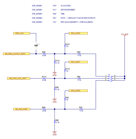
We are in the process of designing a new board where we will only need to transition SOP between Modes 4 and 5. We have very limited PCB area and would like to avoid using a DIP switch as on the 1843BOOST EVM. I noticed in the AWR1843BOOST schematics that TI is level shifting the SOP pins to ~3.0 volts from 3.3 through a resistor-divider network. Is this necessary? Or will it be sufficient to tie the pins directly to pullup/pulldown resistors that current limit the pins? We would just remove SOP2 pullup once the DUT is flashed and ready for deployment.
I checked for voltage and current limitations in the 1843 device datasheet, but did not see any values readily apparent except for hysteresis levels.
Thank you for your help.
Craig.