This thread has been locked.

If you have a related question, please click the "Ask a related question" button in the top right corner. The newly created question will be automatically linked to this question.

IWR1843BOOST: How do i physically access UART RX/PIN connector of IWR1843BOOST

Part Number: IWR1843BOOST
Other Parts Discussed in Thread: MMWAVEICBOOST

Tool/software:

Hi, 

How can I physically access the UART RX/TX pins on the IWR1843BOOST board?

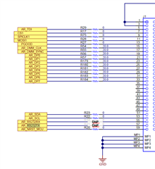
I reviewed the IWR1843BOOST User Guide, and it appears that the J1 connector on the board provides access to these UART signals.

I have a few questions:

  1. Can I use a Samtec cable to directly connect to these pins on J1? If so, could you please suggest a suitable part for the cable or provide a link?

  2. Are any specific switch or SOP settings required on the IWR1843BOOST or MMWAVEICBOOST board to enable UART access through J1?

  3. What will happen to USB connection when I access data via J1. Can i remove the connection? 

  4. Do i need mmWaveICBOOST for this requirement?
  5. Please share if you have a connection diagram similar to this. 

Thanks

Regards

Gayatri

  • Hi Gayatri,

    Please allow us 24 hours to respond.

    Regards

    Ankit

  • Hi Gayatri,

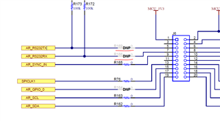
    There are two places on the IWR1843BOOST EVM, from where the UART (RS232) can be physically accessed: 60-pin high density connector J1 and the booster pack connector J6, however, you need to populate few 0ohm resistors to get the connection.

    To access RS232 from J1, you need to populate R33 and R21.

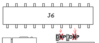
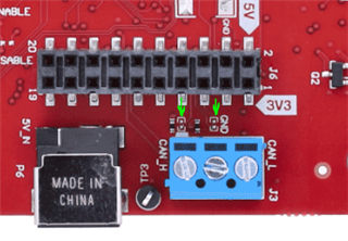
    To access RS232 from J6, you need to populate R169 and R166.

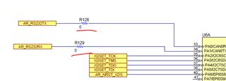
    If you plan to access the RS232 externally and not through the USB (XDS110), it is better to remove the XDS connection in the following way:

    Depopulate R128 and R129.

    If you wish to re-establish the USB connection, you can revert back these changes to the initial state.

    Considering the scopes, I believe, accessing through J6 would be easier as it could be done using jumper wires instead of a high density Samtec cable which is also costly.

    Please let us know if you need any further help.

  • Hi, 

    Thanks for the response . 

    1. What values are required for R169 and R166?

    2. How do i  "Depopulate R128 and R129." on the BOOST board

    3. Is it possible to use MMWAVEICBOOST to access the RX/TX pin without depopulating any connection. What is the right procedure to do this. 

    Thanks 

    Regards

    Gayatri

  • Hi Gayatri,

    Referring to your questions:

    1. R169 and R166 would be 0ohm. You can re-use R128 and R129, once depopulated.

    2. It is a very simple soldering job.

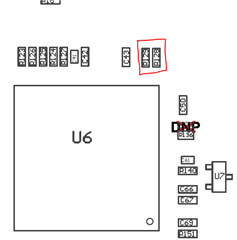
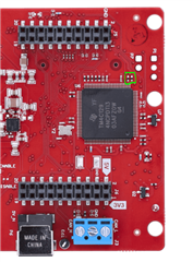
    R128 and R129 are located near U6 at the marked positions. U6 is the XDS110 MCU. Removing R128 and R129 would disconnect the RS232 signals from going into the XDS MCU. You can re-use these 0ohm resistors for R169 and R166 located in the below marked positions:

    3. MMWAVEICBOOST would also require mounting R169 and R166 as you would be connecting the MMWAVEICBOOST using the booster-pack connectors, which would again need R169 and R166 to be populated.

    Thanks and regards,

    Swarnendu