This thread has been locked.

If you have a related question, please click the "Ask a related question" button in the top right corner. The newly created question will be automatically linked to this question.

TMAG5170D-Q1: Please review the schematic

Part Number: TMAG5170D-Q1

Tool/software:

Dear TI experts,

My customer made a schematic using TMAG5170D-Q1. Could you review it ans check some questions?

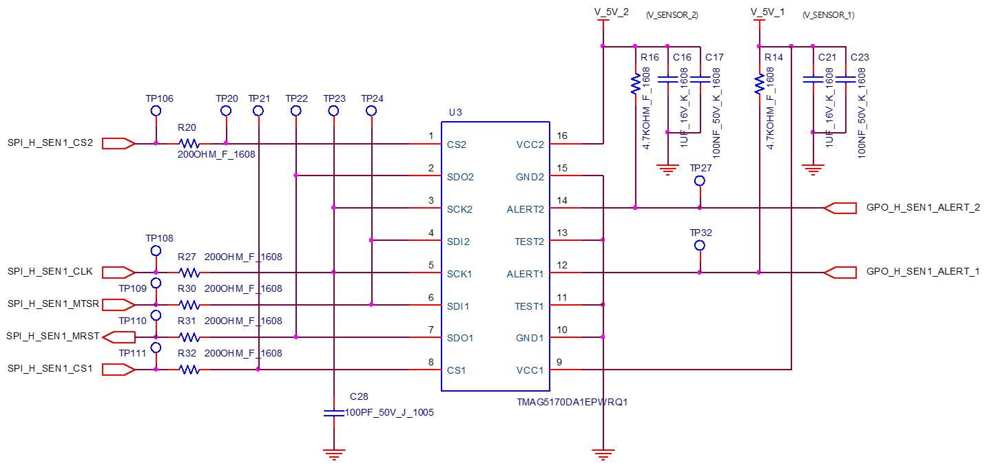
1. Please check that if there are any points to fix for better performance.


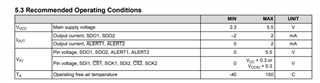
2. Could you check the values of pull up resistors? (R16 and R14) datasheet recommends 10kohm.

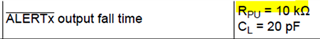
What would be happen if I use 4.7kohm?

Please check these issues. Thanks.

Best regards,

Chase

  • Hi Chase,

    Our team is out today.  We should be able to take a look at your question when we are back in the office starting tomorrow.

    Regards,

    Mekre

  • Dear Mekre,

    Yes I found that Monday is memorial day. Please let me know if there is un update.

    Best regards,

    Chase

  • Chase,

    Thanks for reaching out.  This overall looks okay.  I see that the SDI, SDO, and CLK pins are shared, but they have separate CS control, so this should work.  The termination resistors depend on the rest of the input network for optimal signal quality, but I expect that these values will work.  If adjustments are necessary, it should be possible to tune these values in the lab to obtain the desired behavior.

    A 4.7kOhm pull-up should be okay.  The end effect is that there will be faster rise time compared to 10kOhm when the part releases from a low output, and that there will be about 1.06mA sink current when the output is driven low.  The maximum sink current for these pins is 2mA, so this is still within functional specification for the sensor.

    Thanks,

    Scott