This thread has been locked.

If you have a related question, please click the "Ask a related question" button in the top right corner. The newly created question will be automatically linked to this question.

TUSS4470: Mutual Transmission Between two Ultrasonic Transducers

Part Number: TUSS4470
Other Parts Discussed in Thread: , MSP-EXP430F5529LP

Tool/software:

Hello,

I am designing a ultrasonic anemometer with TUSS4470. I am planing to use 4 ultrasonic transducer for 4 direction. I am thinking of using a TUSS4470 for each transducer in my design, but in this case, what kind of connection should I make to increase the measurement accuracy?

In my design, for example, the ultrasonic signal sent by the north transducer will be received by the south one. In this case, the TUSS4470 of the transducer for the north direction will send the signal and the TUSS4470 of the transducer for the south direction will receive the signal. If I connect the transducer in one direction to the OUT and IN pins of each TUSS4470 in this way, do I need to connect the signal ground between the TUSS4470s? Should such a design be done with a mono static connection as shown in the schematic of BOOSTXL-TUSS4470?

Another idea is to bi-statically connect the transmit side of the TUSS4470 of the north transducer to the north transducer and the receive side to the south transducer, but in this case there should be a direct connection between the 2 TUSS4470s. Because transmission is done from north to south as well as from south to north. How can I make such a bi-static design and what should I pay attention to?

Best Regards,

Metin

  • Metin,

    If you will be using seperate TUSS4470 devices for each transducer, I would suggest using a monostatic configuration on each TUSS4470 device as shown in the EVM.  There is no need to share a ground connection between each of the circuits.  This configuration will also enable you to transmit and receive on all transducers for upstream and downstream data. 

    For bistatic configuration, see the post below.  This could also work, but this type of configuration can still see some ringdown effect of the excitation signal on the RX transducer.  

    BOOSTXL-TUSS4470: Bistatic configuration - Sensors forum - Sensors - TI E2E support forums        

  • Hello Eddie,

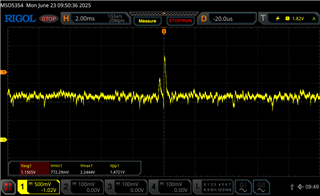
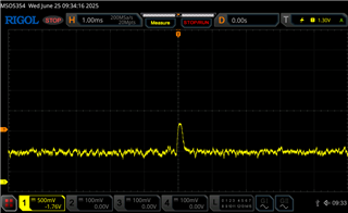
    I used two BOOSTXL-TUSS4470s to exchange signals. In this system, while one BOOSTXL-TUSS4470 acts as a transmitter, I checked the signal transmission by measuring the Vout pin of my other BOOSTXL-TUSS4470 with an oscilloscope. I saw 2 different pulses in the oscilloscope image. I didn't understand why the first pulse was generated while the second pulse was the signal I was sending. I verified that the second pulse was the signal I was sending by putting a barrier between the two transducers. When I put the barrier, the second pulse disappeared while the first pulse was still present. When I stop transmitting from my transmitter BOOSTXL-TUSS4470 board, both pulses are gone. What do you think could be the cause of this.


  • Metin,

    On the transmitter, how many pulses are you sending?  If you send more pulses, do you see any affect on what is received?

  • Eddie,

    I am sending 40 pulses and yes I can see the effect of pulses on received signal. I tried to adjust parameters to fix but notting changed. 

    Actually, when I was testing a while ago, I was only powering the MSP-EXP430F5529LP via USB. Then I connected power to the jack input to power the external drive, but I forgot to remove the main to 5V jumper at J6 and the MSP-EXP430F5529LP burned up. When I checked, there was no problem with the BOOSTXL-TUSS4470 board. I bought a new MSP-EXP430F5529LP and when I reconnected it I noticed this situation. Now I tested it again and this situation persists but when I transmit from the other BOOSTXL-TUSS4470 I don't see this echo but the voltage of the received signal is very low. Could this situation because the TUSS4470 has damaged? The external voltage I applied was 24V. In this case, the TUSS4470 should not be damaged. I cannot understand the cause of the problem.
    The received signal at other BOOSTXL-TUSS4470 is attached. How can I check if TUSS4470 damaged?
  • Metin,

    I would not expect damage to the TUSS4470 at that voltage, unless the device was in "pre driver mode" where the max voltage is 15V.  

    If possible, can you replace the TUSS4470 device on the board?  You can request a sample from the link below.  Scroll all the way to the right and you will see this option.

    TUSS4470 data sheet, product information and support | TI.com 

  • Eddie,

    My sample request declined. So I couldn't replace TUSS4470. I tried different connections and found that there was a problem with the BOOSTXL-TUSS4470 development board. When I examined the board for the cause of the problem, I saw that the only element on the board that could be affected by such a voltage difference could be the TUSS4470. In the current situation, if the TUSS4470s were working correctly, which of the 2 oscillator outputs do you think I would get an image like? I mean, what should the expected signal be?

    Best Regards,

    Metin

  • Metin,

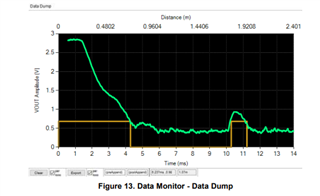
    The expectation is that the echo signal should look like the image below.  I am not sure what could be causing the pulse you see in your first device outside of a damaged device.