Other Parts Discussed in Thread: SYSCONFIG, UNIFLASH
Tool/software:
Hello,
I am trying to modify example motion_and_presence_detection_demo_xwrL64xx-aop_m4fss0-0_freertos_ti-arm-clang for IWRL6432AOPEVM board to make it run without Visualizer APP. I enabled "CLI Removal" and "MPD DPU Enable" options. I added some code to enable PWM outputs when an object is detected. My first placement of PWM pins failed - can't take I2C pins for convenient scope connection on J1 (this was resolved in a different post). I left PWM pins at the default locations, E3 and E4, and the code is running in debug. Now I need help with the following:
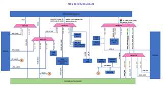
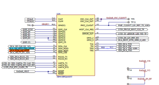
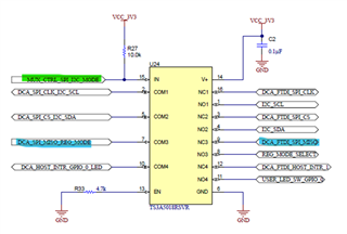
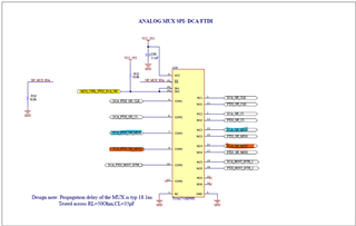
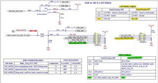
1. The board schematic has a gazillion multiplexers. It makes very hard to track signals without breaking some other signals that are used by the code. What pins should I use for PWM? What switch positions should I set? Where will my PWM signals come out so I can make connection to them? Do I need to do any HW modifications?
2. I need one PWM signal with fixed duty cycle (DC), 50%. I need the other signal with varying DC depending on the distance to the closest object. Do I need to change any configuration default settings (#define ) in any of the files? I found a place in DPC_Execute() function when number of detected objects is calculated. I can't find a place where the distance to an object is calculated reliably. Please navigate me.
3. If I want the two PWM outputs to have a different base frequency, is there any way I do that? Maybe a timer and GPIO for a fixed DC PWM? Can I use a chopper functionality of epwm to make 4kHz from 1kHz?
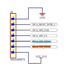
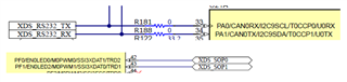
4. When the above is working I want to add CAN communication to the code. Will CAN signal routing to J3 conflict with PWM or any other required signal routing (through multiplexers) on the board?
Alex