This thread has been locked.

If you have a related question, please click the "Ask a related question" button in the top right corner. The newly created question will be automatically linked to this question.

tmp006 suitability

Other Parts Discussed in Thread: TMP006

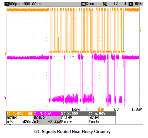
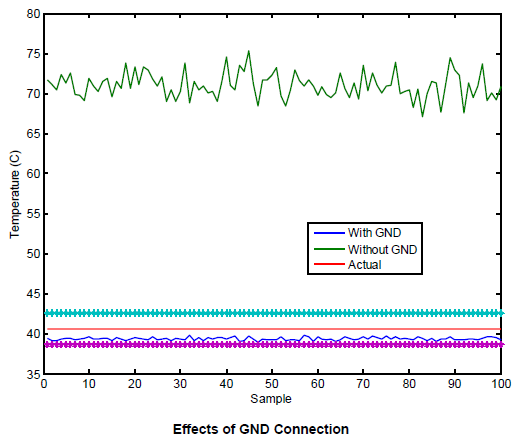
I am considering using the TMP006 for monitoring internal temps of a high power lab grade power system.  However, the internal switching section of this supply radiates considerable noise.  I've had problems previously using thermocouples in this environment, since the system noise caused unreliable readings from thermocouples.  Is the TMP006 a viable alternative or should I consider alternatives?


  •  

    Hello Jim,

    The TMP006 itself should function without issue in a noisy environment as long as our recommended layout is used.

    The real concern is that the power supply's switching noise can couple into the digital communications lines and cause difficulties when reading from/writing to the device. These difficulties can either take the form of highly inaccurate temperature readings or total failures to communicate. Care must be taken to minimize trace lengths, route traces away from noisy components (when possible), and provide adequate GND-connected shielding in order to ensure success.

    The figure below shows an example of I2C lines routed near noisy components. You can clearly see the constant peak-to-peak noise, as well as some severe glitches in the (pink) data line which can cause logic errors that result in incorrect temperature values.

    The graph below illustrates the kinds of temperature errors due to data line glitches that are possible when the I2C lines are routed with no shielding near noisy components. The blue line represents the temperature readings from an I2C temp sensor while the green line is the reference temperature from a thermocouple. The dotted red and blue lines represent an error band of ±2°C. As you can see, errors of ~30°C are possible in this scenario.

    Finally, the figure below shows the improvement once GND-connected shielding is provided for the temp sensor's data lines. The green line shows the temperature reading with shielding that is not connected to GND, while the blue line shows the temperature reading with GND-connected shielding. The red line is the thermocouple reference temperature.

    I hope that this information has been helpful. If you would like to order the TMP006 Evaluation Module, navigate to http://www.ti.com/tool/tmp006evm and click "Order Now."

    Best regards,

    Ian Williams
    Linear Applications Engineer
    Precision Linear and Sensing Products