This thread has been locked.

If you have a related question, please click the "Ask a related question" button in the top right corner. The newly created question will be automatically linked to this question.

TMAG3001: example code for Tmag3001 smartSwitch mode

Part Number: TMAG3001

Tool/software:

I would like to use the TMAG3001 in smart switch mode.  I simply want to push the button and get an interrupt.  I can currently run and read all the values - temp, angles.  These change as I rotate/push the switch.  I would have hoped there was example code that would work with the included 3d printed pushbutton.  I dont see that there is.  That would be very helpful.

  • Hi Larry,

    Thank you for posting to the Sensors forum!

    We do provide example code for the TMAG3001 that can be referenced in order to configure interrupts based on a button press: TMAG3001-CODE-EXAMPLE 

    For a button press application, you can either set a threshold on the Z-axis based on how far the button needs to be pressed to trigger an interrupt, or you can apply a threshold on the magnitude to determine whether a button has been pressed.

    Best,

    ~Alicia

  • Hi - Yes, I have the example code.  As far as I can tell, there is no example that functions as a simple smart switch with the eval pkg (3d printed button w/ magnet).  Im sifting thru the datasheet to figure out which registers are critical for the simple example.  Am I missing the obvious example?

    Larry

  • ahh - I see the rotational example works as I might expect.  

  • Hmm.  And I see that modifying the Omnipolar to Unipolar works as I would want as well.  I think this is a case of: I needed a weekend for everything to sink in.


    Thank you!
    Larry

  • Hi Larry,

    I am glad that you were able to figure things out!

    If you run into any issues or have any other questions, please don't hesitate to reach out.

    Best,

    ~Alicia

  • In playing with the examples, I dont know that Im getting consistent results.  Probably lack of understanding.  Im really looking for simple behavior: Press the 3d printed button and have the intb pulse go active.  Release the 3d printed button and have the intb pulse go inactive.  Any guidance for behavior like that?

  • To clarify, are you wanting the INT pin to pull low and remain low so long as the threshold is crossed? If so, I would recommend using one of the switch modes (unipolar/omnipolar). This way the INT pin will remain low so long as the threshold is crossed. 

    On the other hand, if you are constantly wanting the INT pin to send repeated interrupts so long as the threshold is crossed, I would recommend just using the normal interrupt functionality. An example of this is shown by the W&S mode example, though you would need to change it from angle based interrupts to interrupts based on magnetic fields/magnitude.

    Best,

    ~Alicia

  • Thank you for all of these rapid responses!  Yes - Press, go low and stay low, release, go high.  Im playing with both uni and omni modes.  I see behavior that seems erratic to me.  I have just the Z channel being tracked for thresholds.  Sometimes int goes low and stays low til I release.  Sometimes it spikes low.  Sometimes it goes low and stays low even after I release.  Again, Im using the button that comes with his eval board - thats why Im hoping that you have predictable configs to go with this.

  • Hi Larry,

    Apologies, I forgot that the magnet in the 3D attachment is diametric. This means that when the attachment gets rotated the expected field seen by the Z-axis may change depending on its current position, which may explain why the behavior of the INT pin is not consistent.

    With this attachment (and applications where diametric magnets are used), I would recommend setting a threshold based on magnitude.

    For this mode, I would recommend the following:

    • SENSOR_CONFIG_1
      • MAG_CH_EN = 3h or 7h (you will need at least 2 magnetic channels enabled, though having all three enabled is also okay)
    • SENSOR_CONFIG_2
      • ANGLE_EN = 1h (this will enable magnitude calculations for X and Y)
      • X_Y_RANGE = 1h if using A1 variant (the magnet for the 3D attachment is large so a larger magnetic range is needed)
    • SENSOR_CONFIG_3
      • THR_SEL = 3h (for magnitude threshold/button press)
    • THR_CONFIG_1
      • THRESHOLD1 will be the lower threshold for the magnitude which will set the switch output to OFF (INT pin will return high)
        • Using this same attachment with the TMAG3001EVM the value 0x68 (about 63mT) worked for me
    • THR_CONFIG_2
      • THRESHOLD2 will be the higher threshold for the magnitude which will set the switch output to ON (INT pin will pull low)
        • Using this same attachment with the TMAG3001EVM the value 0x70 (about 68mT) worked for me

    Best,

    ~Alicia

  • Thank you so much!!!  I will try this out!

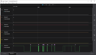
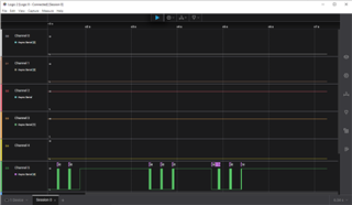
  • Well, it behaves differently.  I think its still angle influenced.  It can generate pulses even if I dont press a button.  Also, the int pulses come in bursts and then stop.  Those triple pulses are when I have the button held down continuously.  Maybe I have the int_mode and related configured incorrectly?  Here is the scope trace of the int pin:

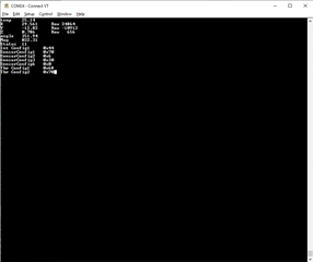
    and here is my relevant register dump

    Again, thank you for your help!  Rare to get this kind of rapid response/support!

  • Hi Larry,

    To use the unipolar switch mode, INT_MODE should be set to 5h. So INT_CONFIG_1 should look something like 0x14.

    Best,

    ~Alicia

  • Hi Alicia, this isnt your problem anymore, but just in case you are bored, we now have the magnet oriented axially.  The Z axis is the one for which I see significant change.  The raw numbers range from about 25000 when unpressed to about 32000 when pressed.  Give or take a thousand on either side.  Any recommendation on how I should configure this for the same basic switch behavior?  

    Larry

  • Hi Larry,

    For this case I would recommend setting THR_SEL to 2h (B field thresholds) instead of 3h which was for magnitude. From here use Threshold3 to set the BOP for the Z-axis and set the BRP using the THR_HYST bits.

    Also, it may be worth looking into using omnipolar switch mode (INT_MODE would just need to be set to 6h) so that you don't need to worry about the polarity of the magnet not being oriented correctly. 

    Best,

    ~Alicia

  • Thank you - please let me know how I can give you a solid review to TI!
    Larry

  • I'm glad I was able to help!

    Best,

    ~Alicia