This thread has been locked.

If you have a related question, please click the "Ask a related question" button in the top right corner. The newly created question will be automatically linked to this question.

AWRL6432: the temperature which is got from rl_fecssTempMeasTrig is abnomal

Part Number: AWRL6432

Tool/software:

Hi TI experts,

While developing a new application for our custom board, we observed inaccurate temperature sensor readings.

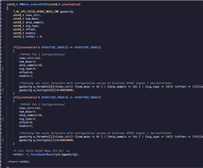
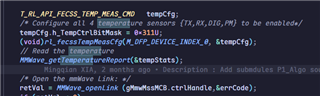
Specifically, the temperature values retrieved via rl_fecssTempMeasTrig sporadically jump from approximately 40°C to around 130°C within a 60ms window – despite stable ambient conditions.

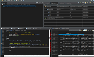
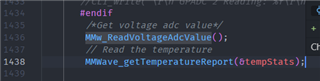
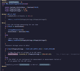
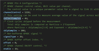
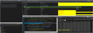
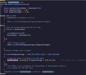
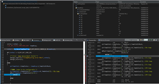
The relevant code section and variable states are captured in the attached snapshot.

After we re-start the sensor, the temperature change to normal.

Have you encountered similar issues? Could you provide recommendations for in-depth debugging?

  • Hi Yongheng, Thanks for reaching out to us over E2E. We have not observed this intermittent behavior with temp sensor.

    Just FYI, we have multiple temperature sensors in different subsystems like Tx, Rx, PM, CLK and Dig. As per the image shared above, it appears that you are observing faulty readings on all the temp sensors. Could you please confirm it?

    Also, you might have given a provision to measure the VBAT(12V) voltage using GPADC pins(external Voltage monitor pins) of AWRL6432 device. Do you see any discrepancies in the measured voltage too?
    The reason for asking the above question is, the temp sensor and external Voltage monitor pins use the same GPADC for measurements.

    Thanks,
    Kundan

  • Hi  Kundan,

    I tested voltage and find that the battery voltage(MMWave_u16ADCRowData) is normal.

    PS: we code to obtain the voltage just before getting temperature.

  • Hi Yongheng,

    Could you please help in performing ABA swap test and confirm that the device is at fault? Once confirmed, we can look at the result and proceed with RMA

    Thanks,
    Kundan

  • Hi Kundan,

    Sorry. I do not understand your means for ABA swap test and what means of RMA. That means change another L6432 chip or swap measurement order?

    If it is the first, we reproduce the issue at different boards. In my view, that should not be HW issue because the boards that we had used for three month do not occur this issue before. 

    And does RMA mean Return Material Authorization? 

  • Hi Yongheng,

    Yes you are correct. What I meant is to mount this unit which shows abnormal behavior on another board which shows absolute fine measurements and check if the issue still persists.

    Yes RMA is Return material assistance. Please confirm if this issue is reproducible on multiple boards.

    Thanks,
    Kundan

  • Hi Kundan,

    We can reproduce the issue with different board. But the multiple boards do not use the same SOC which is why I think this issue may not be the HW issue.

  • Hi Yongheng,

    Could you please confirm the issue rate? Bad boards showing this behavior /total number of boards tested?
    Also, is this SOC sample a production sample or pre-production sample? Could you please share the device marking?

    Our standard procedure is to perform ABA swap test. Could you please perform the following exercise and let us know the results.

    Thanks,
    Kundan

  • Kundan,

    Per talk with customer, here add some more input for your check, and pls help check internal and comment here freely, thanks.

    1. using other previous sw version, doesn't observe the issue. Only have issue using one update sw version. Seems it is SW cause.

    2. Even using update sw, not happen every time, only happen when sensor start is called to have chirping. would possible return to normal if doing sensor stop and start again, also would possible have abnormal later. 

    3. when issue happens, it is strange the returned temp value for TX/RX/PM is similar up to about 135degree, but the value for DIG is -57 which is fully strange. 

    4. Customer has tested on more than 3 their own boards, seems it is not HW cause.

    Will let customer attach the pic of their device, to confirm the device version.

    any unclear pls add here freely, thanks.

    Andy

  • Yongheng,

    pls help provide a pic of your test device marking soon, to let us know about your device version, thanks.

    Andy

  • Hi Andy,

    The device marking is at below picture. And the power and voltage test will be executed later.

  • Yongheng,

    thanks, it is production device. As u mentioned that the issue only happen on specific software, can u let us know more about the software changes with the normal version, thanks. 

    Kundan,

    it is very strange issue, pls help check internally and comment here for next debug. thanks.

    Andy

  • Hi Andy,

    Can we log the following data across multiple trigger cycles(say for ex: 1000 Cycles) into an excel in the Customer's software under same test setup conditions for the failure unit.

    • TX, RX, PM, Dig temperature readings along with one GPADC reading mentioned below.
    • GPADC reading parameters:
      •         chan_ctrl=124;          
                num_meas=4;
                skip_sampls=10;
                sig_type=4;
                offset=0;
                enable=1;
        Config Value of GPADC can be set to 0x00040000

    Thanks,
    Kundan

  • Andy and Yongheng,

    Could you please provide any update on the data requested above for debug.

    Thanks,
    Kundan

  • Hi Kundan,

    Our equipment can only monitor the overall current change of the board. Since we stop detection when a temperature anomaly occurs, the current remains stable. The current testing accuracy is 1mA. Test results show that the current remains the same in both abnormal and normal states.

    Besides, I want to know how to configure the ADC to measurement the temperature? There are four temperature and 8 channels. Do I need configure all 8 channels and read 8 channels?  And how to get the temperature, are there any offset and resolution?

  • Yongheng,

    AWRL6432 only have 2GPADC channel to measure the GPADC pin1/2, mentioned in mail u can refer to SDK mmw demo, search the MMWave_enableGPADC to change the ADC config, call MMWave_readGPADC to get the ADC pin value.

    Read the internal temp sensor and GPADC value for 1000times, and store it in a sheet, share here for check.

    @Kundan,

    pls correct me if any misunderstanding. And the GPADC1/2 are used to monitor the external analog signal, so the value depends on VALEO's HW connection, right?

  • hi Andy/Kundan,

    After do these changes, I can not reproduce the issue. And the data can refer the attachments. 

    And the ADC data Raw data formula is as below:

     Temperature.xlsx

  • Andy and Yongheng,

    I was trying to debug the abnormality with the dig temp sensor. hence, we need to change the GPADC config as mentioned above. Please configure the GPADC as per the parameters shared below. Right now, it looks like you are measuring the external voltage on GPADC pins. Please correct me if I am wrong.

    • GPADC reading parameters:
      •         chan_ctrl=124;          
                num_meas=4;
                skip_sampls=10;
                sig_type=4;
                offset=0;
                enable=1;
        Config Value of GPADC can be set to 0x00040000

    Thanks,
    Kundan

  • Hi Kundan,

    I configure the GPADC reading parameters by MMWave_enableGPADC. And the parameters are all you mentioned before.  So I do not measure the external voltage. I  just do not change the variable name. 

    Regards,

    Yongheng 

  • Kundan,

    with your config, it would measure the internal temp sensors, but which of the four temp sensors would be monitored? Pls help provide code details include where to config and and how to read, to avoid confusion, then Yongheng can do again and provide, really thanks. 

    Andy

  • Hi Andy,

    It is for dig temperature sensor as mentioned in my above reply. Customer needs to replace their existing GPADC config with the above provided configuration and share the raw data without doing any conversion from the GPADC API response.

    By the way from above details shared by Yongheng, it looks like he already changed the config value and the results shared in the xls has the information which we have requested. Unfortunately, customer was not able to reproduce the issue at their end while collecting the data.

    Thanks,
    Kundan

  • Kundan,

    From customer's sheet, the value read through GPADC is 0x5f, the DIG temp sensor value read through rl_fecssTempMeasTrig is 0x22~0x25, any relationship here? Is it reasonable?

    And any comments on next further debug?

    Thanks.

    Andy

  • Hi Kundan/Andy,

    We think this issue might occur during the stop and start radar code process, because the temperature can return to normal after restarting the radar. Furthermore, based on our observation, the first time the temperature anomaly occurred was likely during the first temperature reading after the radar was turned on.  This is because if we detect that the temperature exceeds 125°C for 10 consecutive seconds, we will shut down radar detection. We observed that each time the radar is turned on, the detection is shut down after approximately 10 seconds if issue occur.

    And there are some re-configuration for radar sensor like frame trigger mode...

    Do you think the sensor configuration might influence the temperature measurement?

    Regards,

    Yongheng

  • Hi Yongheng,

    My question is "is it expected to reach 125C temperature under your test conditions(chirp config, ambient temperature)?". Also, it is not normal for the device to measure 130C on one temp sensor and -50C on other.

    Thanks,
    Kundan

  • Hi Kundan,

    "is it expected to reach 125C temperature under your test conditions(chirp config, ambient temperature)?" 

    No, our environment temperature is about 26C and the chirp config also can not cause to reach 125C.

    I agree with your point that it is abnormal. But I can not understand why the external voltage measurement is normal but the internal temperature is abnormal.

    And we also find that the tempstatus also is right value.

    Regards,

    Yongheng

  • Hi Yongheng,

    The temperature sensor could be at fault. Hence, you might be able to measure the correct external voltage readings.

    I wanted to rule out any overflow/underflow in the temperature API response. Hence, I was actually trying to measure the same dig sensor temperature using GPADC API.
    Is this behavior seen on multiple units?

    Thanks,
    Kundan

  • Hi Kundan,

    Yes, we found this issue on multiple units. 

    And we compare the difference between abnormal software and normal software, the main change is SVM data.

    Regards,

    Yongheng

  • Hi Yongheng,

    If it is reproducible across units, can we log similar data as shared above with temp sensor readings along with the GPADC config provided across multiple units and provide us the data?
    Also, what is the change in SW that you are doing between abnormal and normal SW?

    Thanks,
    Kundan

  • Hi Kundan,

    1 For the first question, we need two or three days to complete the data recording. We will provide the data afterward.

    2 Regarding the second question, we have recently implemented some workarounds for this issue.

    There are two workaround methods:

    First method: We add the temperature configuration step before each reading the temperature.

     
    Second method: We remove the temperature acquisition step before MMWave_openLink.

    Both workaround methods are currently functioning as expected based on our latest tests.

    But in my view, these changes do not make sense. Because the changes of code do not impact the logic.

    Back to your second question, the difference between the normal and abnormal cases is that we have integrated the new SVM logic and the data generated by the MBD tools.

    We have also verified that there is no memory overlap issue, as we relocated the SVM-related memory to a different section of the RAM, yet the issue still persists.

    Regards,

    Yongheng

  • Hi Kundan,

    Please check the attachment for other three boards ADC and temperature data.

    ADC_Temp.xlsx

    Regards,

    Yongheng 

  • Hi Yongheng,

    The data seems to be fine for these three boards. Weren't you able to replicate the issue while logging the data?

    Thanks,
    Kundan

  • Hi Kundan,

    As I mentioned before, it is difficult to reproduce if we add some other codes. We try to reproduce recently but failed. We will try it in the future.

    Do you have other idea for this issue?

    Regards,

    Yongheng

  • Hi Yongheng,

    Unfortunately, I can't think of any other cause for this issue. If you are trying to reproduce the issue, I would recommend you trying inside a temperature chamber probably at 70 or 80C.

    Thanks,
    Kundan

  • Hi Kundan,

    Recently, we still try to change some code and reproduce this issue. After moving code RAM, we found the retVal of ADC is -1027(M_DFP_RET_CODE_RFS_GPADC_IFM_INVAL_SAMPLS). Do you know this error meaning? And which parameters will cause this error?

    Regards,

    Yongheng

  • Hi Yongheng,

    This is due to programming invalid number of collect samples field in GPADC config API. The Collect samples should be a non-zero number.

    Thanks,
    Kundan

  • Hi Kundan,

    Are there any other reasons to cause this "M_DFP_RET_CODE_RFS_GPADC_IFM_INVAL_SAMPLS" issue?

    I check the GPADC configuration at IPC RAM and the value "0x820A470" is same with the code configuration when the issue occur.

    The first picture is IPC RAM and the second one is GPADC configuration from code.

    Regards,

    Yongheng 

  • Hi Kundan,

    We reproduce the temperature issue. The data can refer the attachment.

    issue_reproduce.xlsx

    Regards,

    Yongheng

  • Hi Yongheng,

    Thanks for sharing the attachment. Could you please confirm what is B row in the attachment? Which parameter are you measuring?

    Thanks,
    Kundan

  • Hi Kundan,

    The B row is the u16ADCRawData.

    The configuration respect your request above.

    Regards,

    Yongheng

  • Hi Yongheng,

    Just a small question, are you running the GPADC and Temp sensor both at the same time (in parallel)? The reason for asking is the GPADC code doesn't look like it is changed when the digital temperature sensor changes it's reading.
    Also, Do you see any ESM errors while you have observed this temp sensor issue?

    Thanks,
    Kundan

  • Hi Kundan,

    The GPADC and Temp getter are in same thread/task. And we run the temperature just after getting the GPADC value.

    And we don't see the any ESM errors when the issue occur. We implement a DTC for ESM. When the issue appears, we only observe the over temperature DTC.

    Regards,

    Yongheng

  • Hi Yongheng,

    Thanks for providing the clarity on your software sequence. The GPADC API seems to measure the correct value of the temperature. However, the temperature reported by temp sensor API seems to be wrong. I would like to request you for one more set of data on the same unit with GPADC's configured to the following values in parallel to the temperature data.

    • GPADC-1 reading parameters:
      •         chan_ctrl=124;          
                num_meas=4;
                skip_sampls=10;
                sig_type=4;
                offset=0;
                enable=1;
        Config Value of GPADC can be set to 0x00040000
    • GPADC-2 reading parameters:
      •         chan_ctrl=124;          
                num_meas=4;
                skip_sampls=10;
                sig_type=3;
                offset=0;
                enable=1;
        Config Value of GPADC can be set to 0x00020000

    Also from your observations till now, were you able to properly measure the external voltage (VBAT) on these GPADC pins while this issue is being observed?

    Thanks,
    Kundan

  • Yongheng,

    To identify the issue cause is from SW or HW, suggest do below test and feedback here, really thanks.

    1 Upgrade to SDK5.5.2+

    2 take more board for test,

    3 solder the issue device on TI EVM.

    4 Test on their different batch board  

  • Hi Kundan,

    Please kindly check the attachment that follow your mentioned ADC configuration.

    new.xlsx

    Regards,

    Yongheng

  • Hi Yongheng,

    Thanks for sharing the data. We will review internally and get back to you by EOD.

    Thanks,
    Kundan

  • Hi Yongheng,

    This result looks very similar to the before experiment where the ADC codes are staying constant, but the temperature readings are getting corrupted. Were you able to perform any experiments suggested by Andy in the earlier reply?

    Thanks,
    Kundan 

  • Yongheng,

    per call, suggest migrate to sdk5520, test the sw version which can reproduce easily to see if able to reproduce again or not. thanks.

    Andy