Tool/software:
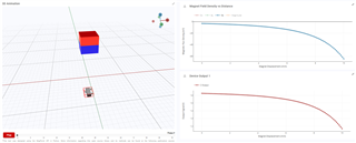
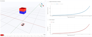
while testing logic for DRV5055, looks like not correct in graphs, could you guide us
Original question:

Tool/software:
while testing logic for DRV5055, looks like not correct in graphs, could you guide us