Tool/software:
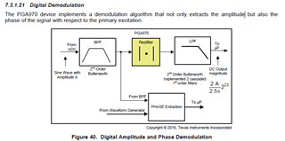
The values I read from demod1 and demod2 are not the same as the voltage coming to the IC between S1P S1N, S2P S2N. How can I find the amplitude of the voltage from the values I read from demod1 and demod2?
This thread has been locked.
If you have a related question, please click the "Ask a related question" button in the top right corner. The newly created question will be automatically linked to this question.
Tool/software:
The values I read from demod1 and demod2 are not the same as the voltage coming to the IC between S1P S1N, S2P S2N. How can I find the amplitude of the voltage from the values I read from demod1 and demod2?
Hi Ozge,
Welcome to E2E! The output of DEMOD1 is the amplitude of the S1/S2 input signals, and the output of DEMOD2 is the phase of the S1/S2 input signals.

The amplitude demodulation depends on the LPF and the BPF you've configured in the PGA970.
The phase can be calculated with M0 software.
Thanks,
Maggie
Hello Maggie,
thank you.
I think demod1 is Va value, demod2 is Vb value. I understand demod1 is result of “s1/s2” but i am wondering how can I calculate Va-Vb/ Va+Vb ratiometric value? Which register?
BR,
ozge
Hi Ozge,
I apologize, I misspoke in my previous message. DEMOD1 is not literally the value of S1 divided by S2. From the datasheet: "The outputs of DEMOD1 and DEMOD2 are the amplitude and phase values of the S1 and S2 gain-stage input signals respectively. The amplitude and phase demodulation algorithm is described in the Digital Demodulation section."
If you would like to calculate a ratiometric value from S1 and S2, you will have to write firmware to do so. PGA970 does not have a specific register to report the ratiometric value you want to read.
Thanks,
Maggie