This thread has been locked.

If you have a related question, please click the "Ask a related question" button in the top right corner. The newly created question will be automatically linked to this question.

LDC5072-Q1: Sensor Design Tool

Part Number: LDC5072-Q1

Tool/software:

I have several questions regarding the use of the LDC5072 tool:

  1. Under the "Sensor Type" section, there are multiple options like Angular Coaxial Type I, Angular Off-Axis, and others. Could someone please help me understand what these configurations mean and how to select the right one?

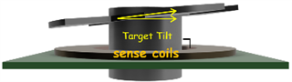
  2. My sensor is placed at the end of the shaft. I would like to know if this positioning affects the performance or if any special considerations are needed.

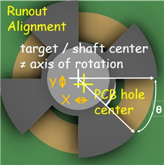
  3. I am currently seeing an angle error of around 4 degrees, but ideally, I want this error to be as low as possible. What steps can I take to reduce the angle error?

  4. I am using the Outer Foil method in the stack-up. Is this appropriate, or should I consider any alternatives?

  5. How do maximum acceleration and maximum speed values impact the tool’s performance or output? Are there recommended limits?

  6. What are the standard values one should enter for manufacturing tolerances?

  7. Regarding the optimizer targets, I haven’t modified any settings. Is it okay to leave them at their default values?

  8. Lastly, for the LDC5072-specific settings, do I need to change any default parameters, or are the existing values suitable for general use?

Your guidance would be highly appreciated.

  • Ajay,

    1. The tool really supports the Angular Co-axial Type 1 coil for the tie being. Future versions of the tool will support others.
    2. End-of-shaft placement is fine as long as the air gap doesn't get too big.
    3. For now the number provided by the tool and the Spice model generated by the tool only serve as an estimates.
      Building and testing a system is the most reliable way to get an answer.
    4.  I'm not sure what you mean by Outer Foil method.
    5.  The max velocity and acceleration are used by the tool to determine the time-varying behavior of the system signals.
      It affects the optimization of the design and is reflected in the Spice models generated by the tool. 
    6. The tool provides some info via the Help buttons, but the actual values are determined by system requirements and manufacturing tolerances.
    7. Default values for optimizer targets are fine.
    8. If by LDC5072-specific-settings you mean internal settings for the device, there aren't any.
      The device is trimmed in production, and the resulting settings aren't adjustable.

  • Hi,
    Could you please explain me difference in coil tilt, coil orientation, target tilt, target orientation. 

  • Ajay,

    Consider that in an ideal system the sense coils and target are exactly parallel to one another, so there is no tilt of either the coil or the target.
    Also consider the target and coils are perfectly centered and symmetrical with respect to the spinning motor shaft.

    If the coils are exactly horizontal but the target is not, then you have target tilt, like shown in the Mechanical Tolerance Help pop-up in the tool as shown just below.

    If the target is exactly horizontal, but the coils are not, there is coil tilt.
    The diagram in the pop-up doesn't seem to show this. In fact, it looks more like target tilt.

    Coil tilt and target tilt cause the air gap to be time-varying, with an average value and a variation.

    The coil/target orientation represents the relative angular orientation between the target and coils at time = 0, before the target starts spinning.

    Regards,
    John

  • Thanks for your reply.
    Runout Orientation & variation phase, please describe these two parameters.

  • Ajay,

    As the Mechanical Tolerance Help window shows, the Runout Alignment is the displacement between the geometric center of the motor shaft and the center of the target. This is shown in the image below as the parameters X and Y.
    The Runout Orientation is the equivalent angle formed by the Runout Alignment of the shaft and the target. This is shown as θ in the graphic below.

    Regards,
    John


  • Hi, I have entered those details, I am getting 16-degree error. Should I still go for board fabrication, or we need to decrease error.

  • Ajay,

    I have never seen the tool give an angle error less than ~4 degrees, regardless of the input parameters.
    The angle estimate provided by the tool is based on a lot of worst-case assumptions that are unlikely to all happen at once.

    To be honest, the best way to move forward is to ignore the tool's reported angle error, build a system based on the design, and measure the performance.

    Regards,
    John