This thread has been locked.

If you have a related question, please click the "Ask a related question" button in the top right corner. The newly created question will be automatically linked to this question.

TPS8802EVM: How to MCU can wakeup from sleep to TPS8802 viceversa ?

Part Number: TPS8802EVM
Other Parts Discussed in Thread: TPS8802

Tool/software:

Hello TI Team,

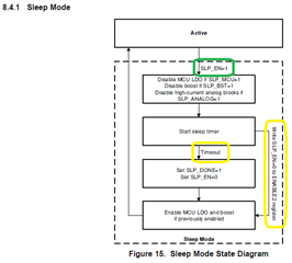
I’m referring to the Sleep Mode functionality described in Section 8.4.1 Sleep Mode of the TPS8802 AFE datasheet [Page 40].

I have configured the TPS8802 to transition from Sleep mode (SLEEP_EN = 1) to Wake-up mode (SLEEP_DONE / SLEEP_EN = 0) using a timer-based approach.

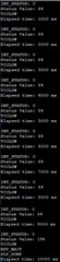
In this setup, I’ve set the sleep timer to 10 seconds. This means the TPS8802 enters Sleep mode (indicated by STATUS1 register showing VCCLOW) for 10 seconds before automatically waking up (indicated by STATUS1 showing SLP_DONE).

The MCU continuously monitors the STATUS1 register to detect the transition from sleep to wake-up.

At boot-up, the MCU calls the function afe_i2c_sleep_timer(10000) to configure the sleep timer for 10 seconds (10000 ms), using the appropriate I2C register settings as specified in the TPS8802 datasheet.

Once the timer is initiated, the MCU repeatedly calls CheckSleepTimeExpiry() to read the STATUS1 register and monitor the sleep-to-wake status.

Please refer to the code snippet below:


void CheckSleepTimeExpiry()
{
    static uint32_t elapsed_time = 0;
    int ret = 0;
    elapsed_time += 1000; // Assuming this function is called every 1 second (1000 ms)
    
    ret = afe_i2c_status_read_reg(TPS880X_REG_STATUS1);
    if(ret == SLP_DONE)
    {
        i2c_write_data(i2c_dev, TPS880X_REG_ENABLE2, 0x84); //SLP_EN = 0 
        StopI2CSleepTimer();
    }
    else if (elapsed_time >= SetSleeptime+5)
    {
        i2c_write_data(i2c_dev, TPS880X_REG_ENABLE2, 0x84); //SLP_EN = 0 
        StopI2CSleepTimer();
        elapsed_time = 0; // Reset the elapsed time
        printk("Abort Timer.\n");
    }
    printk("Elapsed time: %u ms\n", elapsed_time);
}

void afe_i2c_sleep_timer(uint16_t sleep_time)
{
    SetSleeptime = sleep_time;

    // Mask all interrupts, enable INT_MCU
    i2c_write_data(i2c_dev, TPS880X_REG_MASK, 0xFF);

    i2c_write_data(i2c_dev, TPS880X_REG_CONFIG1, 0x37); //SLP_MCU = SLP_ANALOG = SLP_BST = 1

    i2c_write_data(i2c_dev, TPS880X_REG_ENABLE1, 0x3D); // INT_EN = 1

    i2c_write_data(i2c_dev, TPS880X_REG_ENABLE2, 0x85); // SLP_EN = LEDPIN_EN = INT_DIR = LEDSEL = 1 

    if (sleep_time == 0) {
        // Disable the Sleep timer
        i2c_write_data(i2c_dev, TPS880X_REG_SLPTMR1, 0x00);
        i2c_write_data(i2c_dev, TPS880X_REG_SLPTMR2, 0x00);
    }
    else
    {
        // Validate interval
        if (sleep_time < DUALRAYSMOKEAFE_HAL_TIMING_ULPTIMER_MIN_INTERVAL_MS)
        {
            sleep_time = DUALRAYSMOKEAFE_HAL_TIMING_ULPTIMER_MIN_INTERVAL_MS;
        }
        else if (sleep_time > DUALRAYSMOKEAFE_HAL_TIMING_ULPTIMER_MAX_INTERVAL_MS)
        {
            sleep_time = DUALRAYSMOKEAFE_HAL_TIMING_ULPTIMER_MAX_INTERVAL_MS;
        }
    }
    // MSB
    i2c_write_data(i2c_dev, TPS880X_REG_SLPTMR1, sleep_time >> 8);
    // LSB
    i2c_write_data(i2c_dev, TPS880X_REG_SLPTMR2, sleep_time & 0xFF);

    k_timer_init(&si2cSleepTimer, &SleepTimerHandler, nullptr);
    k_timer_user_data_set(&si2cSleepTimer, nullptr);
	StartSleepTimerHandler();
}

uint8_t afe_i2c_status_read_reg(uint8_t reg_addr)
{
    int ret = 0;
    uint8_t status = 0;
    uint8_t status_val = 0;

    ret = i2c_reg_read_byte(i2c_dev, AFE_ADDR, reg_addr, &status);
    if (ret != 0)
    {
        printk("Failed to read Status register\n");
    }
    printk("Status Value: %d\n", status);

    if (reg_addr == TPS880X_REG_STATUS1){
        if (status & VCCLOW)
        {
            printk("VCCLOW\n");
            status_val = VCCLOW;
        }
        if (status & MCULDO_ERR)
        {
            printk("MCULDO_ERR\n");
            status_val = MCULDO_ERR;
        }
        if (status & OTS_ERR)
        {
            printk("OTS_ERR\n");
            status_val = OTS_ERR;
        }
        if (status & OTS_WRN)
        {
            printk("OTS_WRN\n");
            status_val = OTS_WRN;
        }
        if (status & BST_NACT)
        {
            printk("BST_NACT\n");
            status_val = BST_NACT;
        }
        if (status & BST_ERR)
        {
            printk("BST_ERR\n");
            status_val = BST_ERR;
        }
        if (status & INT_UNIT)
        {
            printk("INT_UNIT\n");
            status_val = INT_UNIT;
        }
        if (status & SLP_DONE)
        {
            printk("SLP_DONE\n");
            status_val = SLP_DONE;
        }
    }
    return status_val;
}

Based on the previously provided code, the timer-based sleep-to-wake functionality is working as expected.


Q1: How can I configure the TPS8802 to wake up the MCU using TPS8802 interrupt pin (INT_MCU / GPIO)?

In the current implementation, I enabled the interrupt by writing to the I2C register as follows:

i2c_write_data(i2c_dev, TPS880X_REG_ENABLE1, 0x3D); // INT_EN = 1 (as per datasheet)

Interrupt Pin Connection:

TPS8802 (INT_MCU / GPIO) ----> MCU (GPIO Pin)

However, when I try to read the INT_MCU / GPIO on the corresponding GPIO pin of the MCU, I do not receive any status change on MCU GPIO while tps8802 is going to sleep/wakeup.

Could you please guide me on the correct configuration or additional steps required to trigger and read the interrupt signal from TPS8802 to the MCU?

Q2: How can I wake up the TPS8802 using an MCU GPIO pin (from low to high transition)?

I would also like to configure the setup in the opposite direction, where the MCU can wake up the TPS8802 using one of the MCU GPIO pins by toggling it from LOW to HIGH.

Please advise on the correct register settings or hardware configuration needed to support this functionality.

Thanks & Regards,
Pratik Panchal  

  • Hi Pratik,

    Thank you for providing the details and context for your questions. 

    Regarding Q1, the code that you are using is masking all of the interrupts near the beginning of the afe_i2c_sleep_timer() function.  If you want to see the wakeup flag from TPS8802, you will also want to unmask SLP_DONEM bit7 in the in the MASK register at address 0x03.  Please refer to datasheet sections 8.3.12 and 8.6.4 for additional information.

    Regarding Q2, in order to have the MCU interrupt the TPS8802, the code will need to set INT_EN = 1 and INT_DIR = 1 for those scenarios.  The INT_DIR is bit3 in the ENABLE2 register at address 0x07.  This feature is briefly mentioned in datasheet section 8.3.7 in the explanation of the interconnect driver on the INT_MCU pin and in section 8.3.12.

    Thanks & Regards,

    Jesse

  • Hello Jesse,

    Thank you for your response.

    Based on your suggestion, I have updated the register settings in the afe_i2c_sleep_timer() function as follows:

        // Mask all interrupts, enable INT_MCU
        i2c_write_data(i2c_dev, TPS880X_REG_MASK, 0xFF);
    
        i2c_write_data(i2c_dev, TPS880X_REG_CONFIG1, 0x37); //SLP_MCU = SLP_ANALOG = SLP_BST = 1
    
        i2c_write_data(i2c_dev, TPS880X_REG_ENABLE1, 0x3D); // INT_EN = 1
    
        i2c_write_data(i2c_dev, TPS880X_REG_ENABLE2, 0x8D); // SLP_EN = LEDPIN_EN = INT_DIR = LEDSEL = 1 

    Upon waking up, I updated the SLP_DONEM bit in the MASK register (address 0x03) as shown below:

    i2c_write_data(i2c_dev, TPS880X_REG_ENABLE2, 0x8C); //SLP_EN = 0 
    i2c_write_data(i2c_dev, TPS880X_REG_MASK, 0x7F); // SLP_DONEM = 0
     

    However, I am still not receiving any interrupt or status change from the TPS8802’s GPIO / INT_MCU pin during the sleep-to-wake. I am actively monitoring the corresponding GPIO pin on the MCU, but no signal activity is observed.

    Please find the console output below for your reference, and
    look at the INT_STATUS print, which keeps monitoring the INT_MCU / GPIO.
    In both case, INT_STATUS gets 0. Also, look at the STATUS_1 register bit, on sleep getting VCCLOW and on timeout waking up getting SLP_DONE.


    Thanks & Regards,
    Pratik Panchal

  • Hello Jesse,

    Just a gentle reminder—could you please take a moment to address my query?

    Regards,
    Pratik Panchal

  • Hi Pratik,

    Sorry for the delayed response. 

    In order for your MCU to see the SLP_DONE interrupt on MCU_INT, the TPS8802 needs SLP_DONEM = 0 and STATUS_INT = 1 in the Interrupt Mask Register as well as IINT_DIR = 0 in the Enable1 Register.

    If you set the Sleep Timer Register values before you set SLP_EN = 1, you should see the TPS8802 wake up when the time duration is complete and your MCU will be notified by the interrupt appearing on INT_MCU.  Then, you won't need to set SLP_EN = 0 to force the TPS8802 to wake up.

    Here is an example of how I would change afe_i2c_sleep_timer() assuming that I understand how the function is being called in your context:

    void afe_i2c_sleep_timer(uint16_t sleep_time)
    {
        SetSleeptime = sleep_time;
    
        // Mask all interrupts, enable INT_MCU
        i2c_write_data(i2c_dev, TPS880X_REG_MASK, 0x7F); // SLP_DONEM = 0, STATUS_INT = 1 allows SLP_DONE flag to appear on INT_MCU pin
    
        i2c_write_data(i2c_dev, TPS880X_REG_CONFIG1, 0x37); //SLP_MCU = SLP_ANALOG = SLP_BST = 1
    
        i2c_write_data(i2c_dev, TPS880X_REG_ENABLE1, 0x1D); // INT_EN = 0
    
        // Set the sleep timer before setting SLP_EN:
    
        if (sleep_time == 0) {
            // Disable the Sleep timer
            i2c_write_data(i2c_dev, TPS880X_REG_SLPTMR1, 0x00);
            i2c_write_data(i2c_dev, TPS880X_REG_SLPTMR2, 0x00);
        }
        else
        {
            // Validate interval
            if (sleep_time < DUALRAYSMOKEAFE_HAL_TIMING_ULPTIMER_MIN_INTERVAL_MS)
            {
                sleep_time = DUALRAYSMOKEAFE_HAL_TIMING_ULPTIMER_MIN_INTERVAL_MS;
            }
            else if (sleep_time > DUALRAYSMOKEAFE_HAL_TIMING_ULPTIMER_MAX_INTERVAL_MS)
            {
                sleep_time = DUALRAYSMOKEAFE_HAL_TIMING_ULPTIMER_MAX_INTERVAL_MS;
            }
        }
        // MSB
        i2c_write_data(i2c_dev, TPS880X_REG_SLPTMR1, sleep_time >> 8);
        // LSB
        i2c_write_data(i2c_dev, TPS880X_REG_SLPTMR2, sleep_time & 0xFF);
    
        i2c_write_data(i2c_dev, TPS880X_REG_ENABLE2, 0x85); // Put TPS8802 to sleep with SLP_EN = 1, LEDPIN_EN = LEDSEL = 1, INT_DIR = 0
        
        k_timer_init(&si2cSleepTimer, &SleepTimerHandler, nullptr);
        k_timer_user_data_set(&si2cSleepTimer, nullptr);
    	StartSleepTimerHandler();
    }
    

    I hope that helps.  Please let me know if you continue to encounter an issue.

    Thanks & Regards,

    Jesse

  • Hello Jesse,

    Thank you for your response.

    With your suggestion, it works well.
    Whenever the timer expires and the TPS8802 wakes up or triggers SLP_DONE, the INT_MCU bit is set accordingly.

    INT_STATUS: 0
    Status Value: 0
    re-start tps8802 sleep...
    Sleep Timer Start...
    Elapsed time: 0 ms
    
    INT_STATUS: 0
    Status Value: 64
    VCCLOW
    Elapsed time: 1000 ms
    
    INT_STATUS: 0
    Status Value: 64
    VCCLOW
    Elapsed time: 2000 ms
    
    INT_STATUS: 0
    Status Value: 64
    VCCLOW
    Elapsed time: 3000 ms
    
    INT_STATUS: 0
    Status Value: 64
    VCCLOW
    Elapsed time: 4000 ms
    
    INT_STATUS: 0
    Status Value: 64
    VCCLOW
    Elapsed time: 5000 ms
    
    INT_STATUS: 0
    Status Value: 64
    VCCLOW
    Elapsed time: 6000 ms
    
    INT_STATUS: 0
    Status Value: 64
    VCCLOW
    Elapsed time: 7000 ms
    
    INT_STATUS: 0
    Status Value: 64
    VCCLOW
    Elapsed time: 8000 ms
    
    INT_STATUS: 0
    Status Value: 64
    VCCLOW
    Elapsed time: 9000 ms
    
    INT_STATUS: 1          <------ Yes, INT_MCU gives high bit to MCU 
    Status Value: 192
    VCCLOW
    SLP_DONE
    Elapsed time: 10000 ms
    
    INT_STATUS: 0
    Status Value: 0
    re-start tps8802 sleep...
    Sleep Timer Start...
    Elapsed time: 0 ms
     

    Now, the wake-up from TPS to MCU using the INT_MCU interrupt is working as expected.

    However, for the opposite direction—when the TPS is in sleep mode and the MCU needs to wake it up—
    What configuration changes are required? How can we perform this POC?

    If possible, please provide the code snippet.

    Thanks & Regards,
    Pratik Panchal

  • Hi Pratik,
    Please try my recommendation from the previous reply:


    In order to have the MCU interrupt the TPS8802, the code will need to set INT_EN = 1 and INT_DIR = 1.   The functionality of the interconnect is illustrated in datasheet section 8.3.7 and there is an explanation of the interconnect driver direction at the end of section 8.3.12.

    // Put TPS8802 to sleep with the ability to be awakend by the MCU:
    i2c_write_data(i2c_dev, TPS880X_REG_ENABLE1, 0x3D); // INT_EN = 1 (enable interconnect)
    i2c_write_data(i2c_dev, TPS880X_REG_ENABLE2, 0x8D); // Put TPS8802 to sleep with SLP_EN = LEDPIN_EN = LEDSEL = INT_DIR = 1 (sets direction of interrupt from MCU to TPS8802)


    Thanks & Regards,

    Jesse

  • Hello Jesse,

    Thanks for your response.

    Based on your suggestions, I have updated the configuration to set INT_EN = 1 and INT_DIR = 1.

    Currently, I am using a timer-based sleep approach where the TPS8802 AFE enters a 10-second sleep mode. After the timer expires, the STATUS_1 register correctly reports SLP_DONE.

    Now, I want to perform a POC to see if it’s possible to wake the TPS8802 before the 10-second sleep duration is completed by using the INT_MCU pin. This pin is connected to the MCU’s 1.8V VDD and can be driven high (Manually connect) during the sleep period. [Same, I tried but won't work, it's wakeup as usual defined expiry time duration]

    In this POC, I expect that if I assert the INT_MCU pin before the 10-second timer expires, the STATUS_1 register should immediately indicate SLP_DONE as an early wake-up response.

    Q.1

    Is this approach feasible? Please correct me if my understanding is incorrect.

    Q.2

    Could you please suggest an alternative method? Specifically, is it possible to put the TPS8802 AFE into sleep mode directly, without using the sleep timer, and wake it up using a high signal from the MCU on the INT_MCU pin?

    Kindly provide your suggestions.

    Thanks & Regards,
    Pratik


  • Hi Pratik,

    A.1:  See Figure15 in section 8.4.1 of the datasheet describing the Sleep Mode state diagram.  The TPS8802 sleep feature is intended to be used with the sleep timer and responds to either the expired timer or SLP_EN = 0.  (When INT_EN = INT_DIR = 1, then INT_MCU is an input to the interconnect with output to INT_UNIT intended to pass an interrupt signal from the MCU from one TPS8802 to other alarms in a mains-wired smoke alarm system.)

    A.2: The method that you are asking about would not have all of the benefits of sleep mode mentioned in the bullet points of datasheet section 8.4.1 (be sure to carefully consider the benefits), but if this suits your usage case, an alternative method would be to have the MCU disable features using the register bits and then re-enable them by having the MCU enable the features using register writes.

    Thanks & Regards,

    Jesse

  • Hello Jesse,

    Thank you for your response.

    Regarding point A.1, based on my understanding, when we drive the INT_MCU pin high from the MCU, the INT_UNIT will also output a high signal. Could you please confirm if this understanding is correct?

    However, in our application, we do not require the interconnect or one-go-all-go feature. Our primary need is to wake up the TPS8802 from sleep mode using an MCU GPIO interrupt. Could you please guide us on how to configure this wake-up mechanism, specifically from the MCU side, without involving the interconnect functionality?

    Regarding point A.2, you mentioned an alternative method (without using timer-based sleep) that involves the MCU enabling or disabling specific register bits. Could you please clarify which exact register you are referring to? Additionally, you noted that there may not be any significant benefit from the features listed in section 8.4.1. Could you please confirm whether we should drop this approach entirely, or if it is still viable, kindly provide suggestions on how this method should be correctly implemented?

    Thanks & Regards,
    Pratik Panchal

  • Hi Pratik,

    Follow-up on A.1:  That is correct.  As described in the datasheet section 8.4.1 (and illustrated in Figure 15), the sleep mode wakes up either do to an expired timer or the SLP_EN bit being cleared like you were using previously to force the TPS8802 to wake up.

    Follow-up on A.2:  The ENABLE1, ENABLE2 and CONTROL registers provide i2c control over the device features that sleep mode would normally disable as described in Figure 8.  You can manually disable them without using the sleep mode.  This Section 8.4.1 text describes the benefits of using the TPS8802 sleep mode and why an alternate method can consume more power:

    "Sleep mode reduces power consumption in three ways:
    • by quickly disabling analog blocks
    • by powering off the boost and MCU LDO during sleep mode
    • by allowing the MCU to enter its lowest power idle state


    Every I2C transaction takes time and consumes a small amount of power. The SLP_ANALOG bit configures
    sleep mode to disable high-power amplifiers and drivers simultaneously when entering sleep mode. This
    functionality can save several I2C transactions and reduces time that the amplifiers and drivers are idly enabled.
    The device may require the boost converter and MCU LDO while the microcontroller is performing sensing and
    testing operations, but may not require the boost and MCU LDO while the microcontroller is in its idle state.
    SLP_BST and SLP_MCU disable the boost converter and MCU LDO during sleep mode. If the boost converter
    and MCU LDO were previously enabled, they are re-enabled when sleep mode is exited. This process reduces
    system current consumption caused by the MCU LDO and boost converter while preventing a system brown-out
    if the MCU loses power, because the exit of sleep mode returns power to the MCU.

    During sleep mode operation, the MCU can enter its lowest power idle state and monitor a GPIO pin for the
    SLP_DONE interrupt signal. This monitoring allows the MCU clocks to be disabled as the sleep timer signals the
    MCU to wake up after a precise programmed time."

    I am going to have the regional team reach out to you via email to continue this discussion. 

    Thanks & Regards,

    Jesse