This thread has been locked.

If you have a related question, please click the "Ask a related question" button in the top right corner. The newly created question will be automatically linked to this question.

IWR6843AOP: Improve max range detection in 3D Tracking People Example (Wall mount)

Part Number: IWR6843AOP

Tool/software:

I'd like to revive this thread, as I've resumed work on the project.

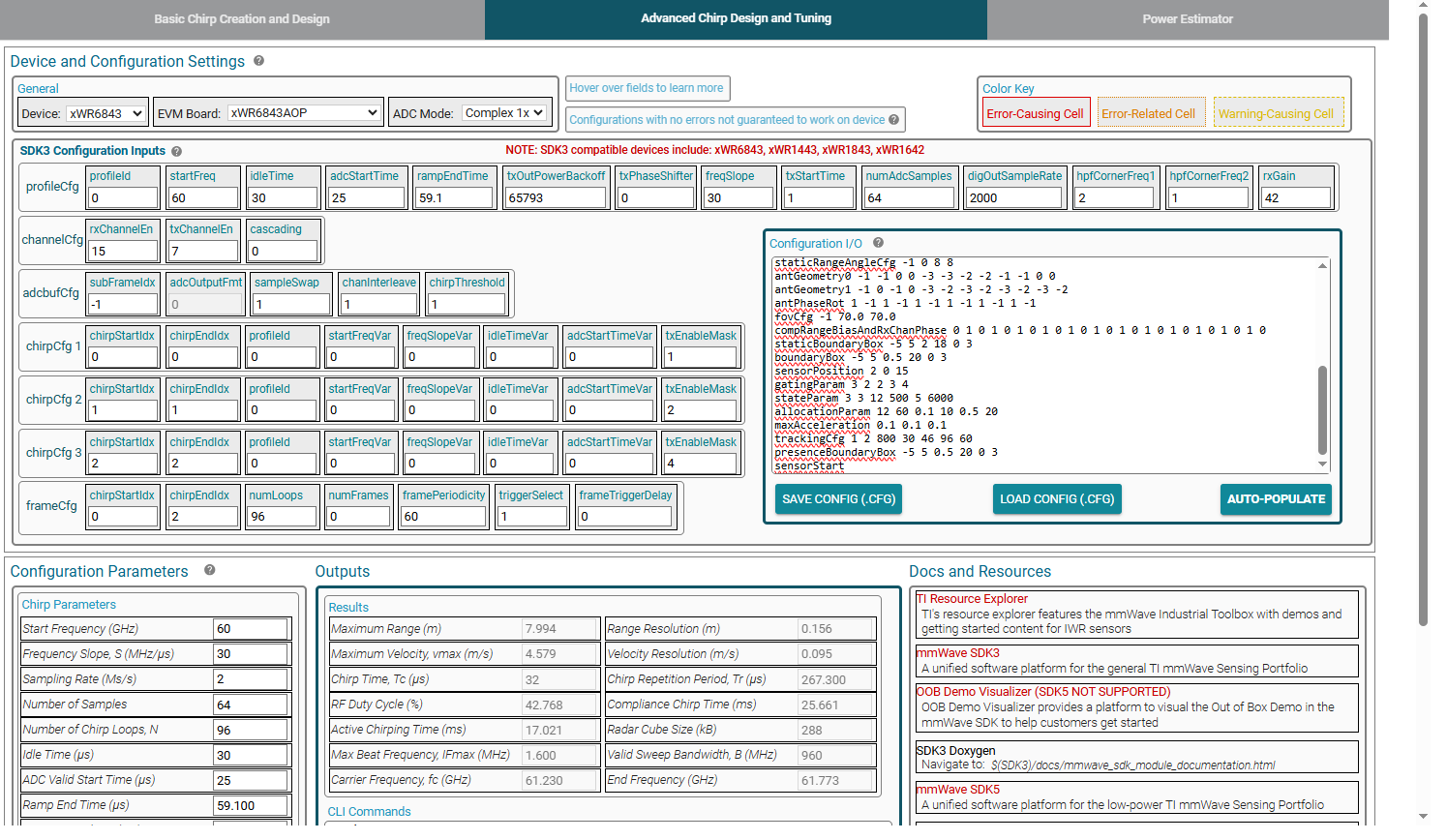
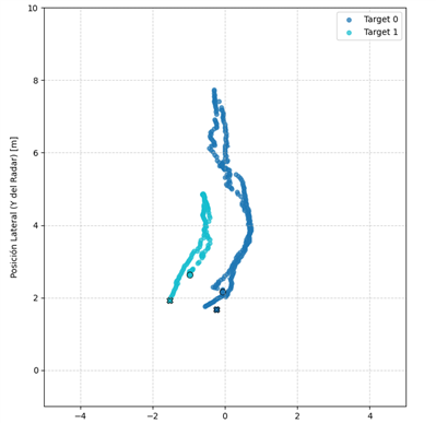
With the current configuration, I've been able to detect objects accurately up to around 12 meters. Beyond that distance, detection is lost. I’ve tried adjusting the frequency slope, but I haven’t observed any noticeable improvement in the detection range.


quote to my last post related:

Hi everyone,

I've been working with the IWR6843AOP sensor using the 3D People Tracking demo, with the sensor mounted on a wall at a 15° downward tilt. I've run several tests, adjusting the detection and tracking parameters across different configurations. I'm using the IWR6843AOP EVM board and configuring its parameters based on the documentation in Section 4 of the 3D People Tracking Demo Detection Layer Tuning Guide.

However, in nearly all cases, the maximum detection range caps at around 12.5 meters. Beyond this distance, no point cloud is detected, and no target is tracked.

In my most recent test, I increased the transmission power by configuring the txOutPowerBackoff to 0 dB, which did result in extended detection up to 14 meters in some cases—but with significantly more background noise throughout the reading.

I’d like to understand whether:

    There’s something potentially misconfigured in my setup that's causing this limitation, or
    The sensor is inherently limited to around 12.5 meters in most real-world scenarios, despite parameter tuning.

Any insights or suggestions would be greatly appreciated!


Also, can anyone tell me what software is being used to obtain sensor metrics based on the .cfg file shown in the previous post? That tool looks quite helpful.

  • Hi,

    Please post your entire cfg file. Is the problem that you see ABSOLUTELY no detections beyond 12 meters? Or that the detection rate seems to diminish beyond 12 meters?

    Best,

    Nate

  • This is my cfg, 

    sensorStop
    flushCfg
    dfeDataOutputMode 1
    channelCfg 15 7 0
    adcCfg 2 1
    adcbufCfg -1 0 1 1 1
    lowPower 0 0
    profileCfg 0 60.00 30.00 25.00 59.10 65793 0 30 1 64 2000.00 2 1 42 
    chirpCfg 0 0 0 0 0 0 0 1
    chirpCfg 1 1 0 0 0 0 0 2
    chirpCfg 2 2 0 0 0 0 0 4
    frameCfg 0 2 96 0 60.00 1 0
    dynamicRACfarCfg -1 4 4 2 2 8 12 4 12 10 8.00 0.40 1 3
    staticRACfarCfg -1 6 2 2 2 8 8 6 4 8.00 15.00 0.30 0 0
    dynamicRangeAngleCfg -1 0.75 0.0010 1 0
    dynamic2DAngleCfg -1 3.0 0.0300 1 0 1 0.30 0.85 8.00
    staticRangeAngleCfg -1 0 8 8
    antGeometry0 -1 -1 0 0 -3 -3 -2 -2 -1 -1 0 0
    antGeometry1 -1 0 -1 0 -3 -2 -3 -2 -3 -2 -3 -2
    antPhaseRot 1 -1 1 -1 1 -1 1 -1 1 -1 1 -1
    fovCfg -1 70.0 70.0
    compRangeBiasAndRxChanPhase 0 1 0 1 0 1 0 1 0 1 0 1 0 1 0 1 0 1 0 1 0 1 0 1 0
    staticBoundaryBox -5 5 2 18 0 3
    boundaryBox -5 5 0.5 20 0 3
    sensorPosition 2 0 15
    gatingParam 3 2 2 3 4
    stateParam 3 3 12 500 5 6000
    allocationParam 12 60 0.1 10 0.5 20
    maxAcceleration 0.1 0.1 0.1
    trackingCfg 1 2 800 30 46 96 60
    presenceBoundaryBox -5 5 0.5 20 0 3
    sensorStart


    I don’t see any detections beyond 12 meters — no point cloud and no targets.

    I would like to use the software shown in the image to try to reach the desired metrics for my application, but I don't know what it is. where can i found it?

  • Hi,

    https://dev.ti.com/gallery/view/mmwave/mmWaveSensingEstimator/ver/2.5.0/

    This is how you can see the view in the image.

    You need to change the frequency slope - right now it's set to only detect at 8m. I know you said you tried that, but the config you posted above is only for 8m.

    Do you not see the detection range change when you modify frequency slope?

    best,

    Nate

  • Hi Nate, 

    I have used the software to find a suitable slope value for my application, but I have some doubts and results to discuss.

    First, is the slope value arbitrary, or is it related to other parameters?

    I’ve conducted tests using a slope value that gives me the desired range, but I’m now encountering an issue where two tracks are generated for a single person. For a significant portion of the trajectory, two tracking IDs are assigned to the same person in the area. Since this seems to be caused by modifying the slope frequency, could you provide recommendations on how to mitigate this issue?

    We performed a test where a person walked forward up to approximately 8 meters and then returned along the same path. The results are shown in the graph below.

    The blue points represent the correct trajectory of the person.

    The light blue points correspond to a ghost track or reflection, which appears slightly to the left of the true path.

    Notably, there is only a table in that area—no nearby wall that could explain a strong reflection.

    We have already tried tuning the following parameters:

    snrThre

    snrThreObscured

    pointsThre

    We've also attempted to filter by confidence level on a per-frame basis, but the reflected track consistently reports a confidence above 0.80, making it difficult to discard based on that metric alone.

    sensorStop
    flushCfg
    dfeDataOutputMode 1
    channelCfg 15 7 0
    adcCfg 2 1
    adcbufCfg -1 0 1 1 1
    lowPower 0 0
    profileCfg 0 60.75 30.00 25.00 59.10 65793 0 24.4 1 96 2950.00 2 1 40
    chirpCfg 0 0 0 0 0 0 0 1
    chirpCfg 1 1 0 0 0 0 0 2
    chirpCfg 2 2 0 0 0 0 0 4
    frameCfg 0 2 96 0 60.00 1 0
    dynamicRACfarCfg -1 4 4 2 2 8 12 4 12 10 8.00 0.40 1 3
    staticRACfarCfg -1 6 2 2 2 8 8 6 4 8.00 15.00 0.30 0 0
    dynamicRangeAngleCfg -1 0.75 0.0010 1 0
    dynamic2DAngleCfg -1 3.0 0.0300 1 0 1 0.30 0.85 8.00
    staticRangeAngleCfg -1 0 8 8
    antGeometry0 -1 -1 0 0 -3 -3 -2 -2 -1 -1 0 0
    antGeometry1 -1 0 -1 0 -3 -2 -3 -2 -3 -2 -3 -2
    antPhaseRot 1 -1 1 -1 1 -1 1 -1 1 -1 1 -1
    fovCfg -1 70.0 70.0
    compRangeBiasAndRxChanPhase 0 1 0 1 0 1 0 1 0 1 0 1 0 1 0 1 0 1 0 1 0 1 0 1 0
    staticBoundaryBox -1 2 0.5 16 -5 5
    boundaryBox -1 2 0.5 16 -5 5
    sensorPosition 0 15 0
    gatingParam 4 2 2 2 4
    stateParam 2 3 12 200 2 600
    allocationParam 35 160 0.1 20 0.5 25
    maxAcceleration 0.2 0.2 0.2
    trackingCfg 1 2 800 30 46 96 60
    presenceBoundaryBox -1 2 0.5 16 -5 5
    sensorStart


    6661.target_0.csv
    6661.target_1.csv