This thread has been locked.

If you have a related question, please click the "Ask a related question" button in the top right corner. The newly created question will be automatically linked to this question.

AWR2944: False peaks exist in the fixed RangeBin in the large target state

Part Number: AWR2944

Tool/software:

Hi TI teams:

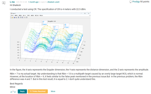
In the recent test, I discovered a problem existing in the spectrum,I used RTS to create a target of 30m-30dBsm-0Kph,This target can be correctly observed in the 2D spectrum

However, there will be false peaks at the 4th and 7th bins after this target peak,Even if the waveform configuration is changed and the scale of the RangeBin is adjusted, problems still occur at the 4th and 7th bins

eg:

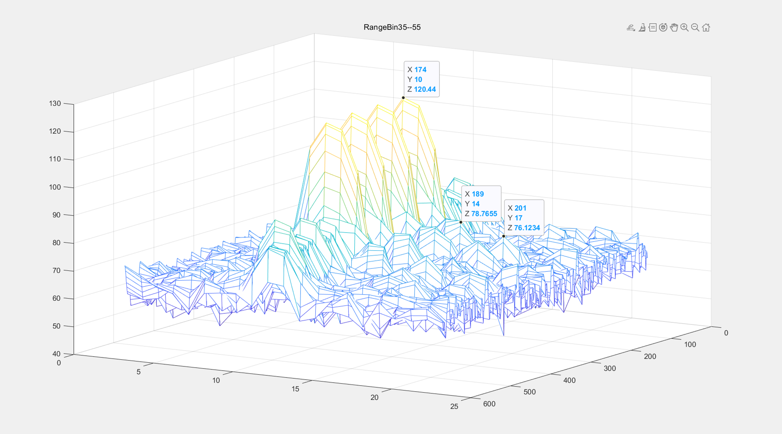
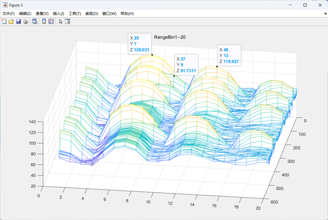
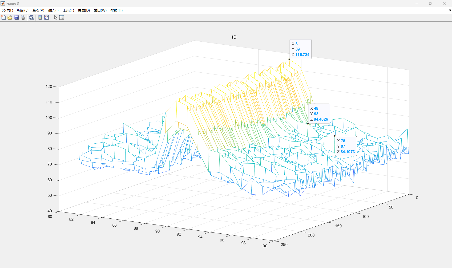
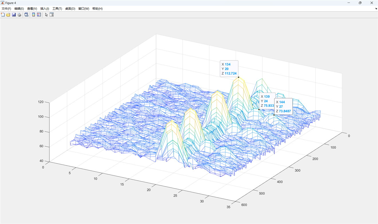
The first waveform :The drawing coverage range is 35-55 bins(so the actual Bin is 45),There are false peaks at locations 14 and 17

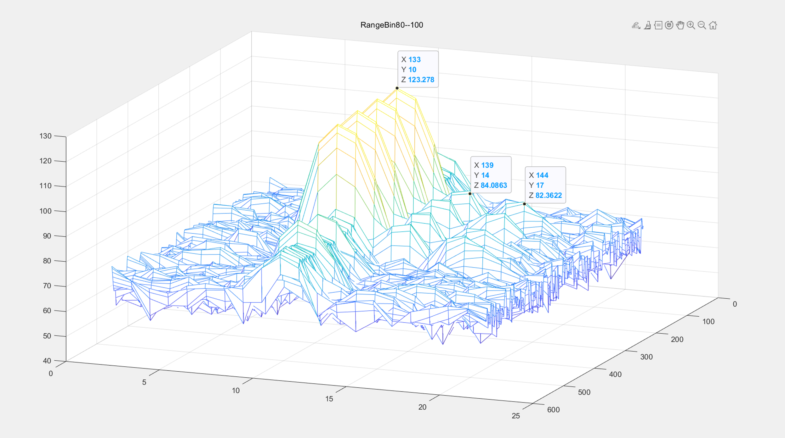
The second waveform :The drawing coverage range is 80-100 bins(so the actual Bin is 90),There are false peaks also at locations 14 and 17

Regarding the above situation, In my understanding, if these two targets really exist in the environment, then as the slope of my waveform changes, their differences should also change together, rather than being fixed at 4 and 7 differences from the real targets.

This situation can be reproduced by using TI2944EVM and OOB-Demo, and by using adv-chirp-adv-frame for Profile.

From what aspects can I analyze this problem? Thank you!

Best Regards
Minxi
  • Hi Minxi,

    If I understand correctly the X dimension is range, what is the other dimension, angle?

    I can see that there are additional peaks in the Y dimensions at offsets from the main peak. Then you changed the objects frequency by changing the slope, this will only affect the rangle (X) dimension, so your X values changed for all the peaks. Were you expecting the Y values for any peak to change with that? 

    Please point out if I am incorrect. 

    Regards,
    Shailesh

  • Hi Shailesh

    First, let's discuss this picture.,For this schematic diagram,The Y-axis represents RangeBin,and the X-axis represents DopplerBin. 

    We used TX's phase shift.so,The X-axis will also experience a frequency shift.

    So, now we are discussing the issue in the dimension of distance. I changed the slope, and the Bin(Y) of the actual target, which was originally 35 + 10 = 45, changed to 80 + 10 = 90. However, the two small peaks following the actual target (Y = 14 and Y = 17) should also have changed, but the actual data did not change. Therefore, I suspect whether it is a problem caused by the radar system itself.

    I wonder if my description is clear enough.If you have any other questions that you don't understand, please feel free to contact me. Thank you very much.

    Best Regards
    Minxi
  • Hi Shailesh

    Sorry, there was an error in my previous reply. The offset on the X-axis is due to the use of stepped frequency, not because of the phase shift of the antenna.

    Best Regards
    Minxi
  • Thank you for the clarification, Minxi. 

    Can you confirm that you are not changing the sampling rate, only the slope between the two cases? And what is the sampling rate being used? What are the range processing steps, i.e. zero padding, windowing and fft?

    Can you try to see if the issue is visible when you don't do the stepped frequency? Just do a normal range-doppler spectrum?

    Regards,
    Shailesh

  • Hi Shailesh

    I'm certain that only the slope and the start-frequency have changed between the two waveforms.

    Their sampling rate is 25000 ksps and the number of sampling points is 1000.

    When conducting 1D and 2D processing, a 60dB Chebyshev window was employed.

    Regarding the test of disable step frequency,I will reply after I have the test results.

    Thank you .

    Best Regards
    Minxi
  • Hi Minxi,

    So, if I assume you are doing a 1024 point FFT (please confirm), the 4 bins offset will mean 97kHz offset and 7 bins will mean 170KHz offset from the main tone. This does not match with any known spurs in the device as per the document: https://www.ti.com/lit/er/swrz102c/swrz102c.pdf. Do you see the spurs on only one side of the main tone, or are there peaks at -4 and -7 offsets too? 

    Can you help us understand what object is present in the scene? Are there multiple objects present, do all the objects show these peaks? Can you experiment using a reflector and understand if it shows for all distances and for multiple objects?

    Regarding the test of disable step frequency,I will reply after I have the test results.

    Thanks, that is useful.

    Regards,
    Shailesh

  • Hi Regards,

    Now that the test on the step frequency has been completed, I will share the results with you.

    1.As you said, we will perform a 1024-point FFT. And the spurs on only one side of the main tone(+4 and +7 offsets)

    2.The peak value in the 2D spectrum is my set target, which is the 30m30dBsm0Kph target set by Radar target simulator.There is only this one goal.It is precisely because of such a target setting that the emergence of the two false peaks has caused us great trouble.

    3.After disabling the step frequency, the false peak still exists, but there is no offset in the Doppler dimension.

    The two pictures above show the result of turning off the step frequency.

    The two pictures above show the result of activating the step frequency.

    It doesn't seem to be the root cause.

    Looking forward to your reply. Thank you.

    Best Regards
    Minxi
  • Hi Minxi. Thanks for sharing the results.

    Have you been able to confirm that the false peaks are not RTS issue? Can you try to keep a reflector in front of the radar in the same configuration and see if you can see any spurs?

    Can you share your chirp configurations? Just to see if something is abnormal. We have seen sometimes dependency on sampling rates also, can you try changing that as well?

    Regards,
    Shailesh

  • Hi,Regards

    Thanks for your response.

    Next, I will use CR to conduct this test again.

    And,This is the configuration that I am using.

     "sensorStop \n\r",
        "flushCfg \n\r",
        "dfeDataOutputMode 5 \n\r",
        "channelCfg 15 15 0 \n\r",
        "adcCfg 2 0 \n\r",
        "adcbufCfg -1 1 0 0 1 \n\r",
        "lowPower 0 0 \n\r",
        "profileCfg 0 77 267 7 57.14 0 0 70 1 384 13349 0 0 158 \n\r",
        "profileCfg 1 77 7 7 20.81 0 0 10 0 384 28000 0 0 158 \n\r",
        "advChirpCfg 0 1 0 0 0 0 0 0 0 0 0 2 1 0 0 0 \n\r",
        "LUTDataCfg 0 0 1 \n\r",
        "advChirpCfg 1 1 0 1 -550000 -550000 0 0 0 0 16 1 0 2 0 0 \n\r",
        "LUTDataCfg 1 0 \n\r",
        "advChirpCfg 2 1 0 0 100 0 0 0 1 0 32 1 0 0 0 0 \n\r",
        "LUTDataCfg 2 0 \n\r",
        "advChirpCfg 3 1 8 1 0.01 0.02 0 0 8 2 48 4 0 0 0 0 \n\r",
        "LUTDataCfg 3 0.01 0.03 0.00 0.02 \n\r",
        "advChirpCfg 4 1 0 0 0.02 0 0 0 1 0 64 1 0 0 0 0 \n\r",
        "LUTDataCfg 4 0 \n\r",
        "advChirpCfg 5 1 0 0 0 0 0 0 1 0 80 1 0 0 0 0 \n\r",
        "LUTDataCfg 5 15 \n\r",
        "advChirpCfg 6 1 0 0 0 0 0 0 1 0 96 1 0 0 0 0 \n\r",
        "LUTDataCfg 6 0 \n\r",
        "advChirpCfg 7 1 0 0 2.815 0 0 0 6 1 112 6 0 0 0 0 \n\r",
        "LUTDataCfg 7 0 0 0 0 0 0 \n\r",
        "advChirpCfg 8 1 0 0 5.625 0 0 0 6 1 128 6 0 0 0 0 \n\r",
        "LUTDataCfg 8 0 180 0 180 0 180 \n\r",
        "advChirpCfg 9 1 0 0 11.25 0 0 0 6 1 144 6 0 0 0 0 \n\r",
        "LUTDataCfg 9 0 300 240 180 120 60 \n\r",
        "advChirpCfg 10 1 0 0 22.50 0 0 0 6 1 160 6 0 0 0 0 \n\r",
        "LUTDataCfg 10 0 240 120 0 240 120 \n\r",
        "advFrameCfg 2 0 10 1 0 2 \n\r",
        "subFrameCfg 0 0 0 0 96 250 0 1 1 250 \n\r",
        "subFrameCfg 1 0 0 0 384 250 0 1 1 250 \n\r",
        "guiMonitor -1 2 1 0 0 0 1 \n\r",
        "cfarCfg 0 1 3 16 0 0 1 24.0 0 7 0 1 \n\r",
        "cfarCfg 0 0 3 16 0 0 1 15.0 0 7 0 1 \n\r",
        "cfarCfg 1 1 3 16 0 0 1 24.0 0 7 0 1 \n\r",
        "cfarCfg 1 0 3 16 0 0 1 15.0 0 7 0 1 \n\r",
        "compressionCfg 0 1 0 0.5 8 \n\r",
        "compressionCfg 1 1 0 0.5 8 \n\r",
        "intfMitigCfg 0 15 18 \n\r",
        "intfMitigCfg 1 15 18 \n\r",
        "localMaxCfg 0 6 40 \n\r",
        "localMaxCfg 1 6 40 \n\r",
        "antGeometryCfg 1 0 1 1 1 2 1 3 0 2 0 3 0 4 0 5 1 4 1 5 1 6 1 7 1 8 1 9 1 10 1 11 0.5 0.8 \n\r",
        "antennaCalibParams 0 1 0 1 0 1 0 1 0 1 0 1 0 1 0 1 0 1 0 1 0 1 0 1 0 1 0 1 0 1 0 1 \n\r",
        "measureRangeBiasAndRxChanPhase 0 1.5 0.2 \n\r",
        "analogMonitor 0 0 \n\r",
        "calibData 0 0 0 \n\r",
        "aoaFovCfg -1 -90 90 -90 90 \n\r",
        "lvdsStreamCfg -1 0 1 0",
        "sensorStart \n\r",
    Best Regards
    Minxi
  • Next, I will use CR to conduct this test again.

    Thanks Minxi.

    "profileCfg 0 77 267 7 57.14 0 0 70 1 384 13349 0 0 158 \n\r",
        "profileCfg 1 77 7 7 20.81 0 0 10 0 384 28000 0 0 158 \n\r",

    Minxi, in your previous comments it was mentioned that you are using 1000 samples and the rate is 25000 ksps, but that does not match with the profile configs shown here. Can you confirm what is the correct configuration being used? 

    Regards,
    Shailesh

  • Hi,Shailesh

    Sorry, I forgot to mention something.

    My reply to you is "Ti-Demo-Profile", with the addition of step frequency.(Of course, the configuration for disabling the step frequency was also tested as per your suggestion.)

    And,Regarding the 25000 ksps configuration, it is a waveform that we designed ourselves.

    For these configurations, I conducted ADC sampling for each one, and the results were all the same.(Due to the different waveform configurations, the RangeBin values corresponding to the actual targets will vary. However, all of them will show false peaks at the fourth and seventh bins after this RangeBin.)

    Best Regards
    Minxi
  • Hi Minxi,

    Okay, I wanted to check also if your adc start time or ramp end time configurations are too less in your profile configurations. 

    I think it will be useful to check with the CR and also if there is a dependency on sampling rate. 

    Regards,
    Shailesh

  • Hi Shailesh

    I conducted a test using CR. The specification of CR is 4 meters with 22.5 dBm.

    In the figure, the X-axis represents the Doppler dimension, the Y-axis represents the distance dimension, and the Z-axis represents the amplitude.

    RBin = 7 is my actual target. My understanding is that Rbin = 13 is a multipath target caused by an overly large target RCS, which is normal. However, at the location of Rbin = 9, it feels similar to the false peak mentioned in the previous issue.But  in the previous problem, the Rbin difference was 4 and 7. But in this test result, it is equal to 2. I don't quite understand this.

    Best Regards
    Minxi
  • Hi Minxi, 

    Can you see the spurs if you only perform range FFT and not Doppler? I am also not sure if you should see the peaks in doppler as CR is a static object, correct? Trying to see if the false peak is a processing artifact.

    On the RF side, this does not match with our expectation if the configurations are all valid. As indicated before, some invalid configuration of idle time, adc start time or ramp end time can also result in additional noise/spurs. Requesting again to confirm this as per your profile configuration, previously you have shared only TI profile configuration.

    Regards,
    Shailesh

  • Hi Shailesh

    This picture represents the result of range FFT. The X-axis indicates Chirp_num and the Y-axis indicates RangeBin.

    I understand that there are still the so-called false peaks that we have described.However, from the graph, it can be seen that not all Chirps exhibit this false peak clearly.

    For waveform configuration, we will illustrate it with the graphical results:

    start_freq = 76.899Ghz
    start_freq_delta_differ_value = 1.29Mhz
    idle_time = 8us
    adc_start_time = 2.6us
    ramp_end_time = 49us
    slope = 10.7Mhz/us
    tx_start_time = -1.8us
    adc_sample_rate = 25000ksps
    adc_samples = 1024
    chirp_num = 212
    vco_select = 0
    Could you please help me analyze whether there are any issues with this configuration? Thank you.
    By the way, I have a question. Suppose I have multiple waveform configurations with different slopes and idle times. Then, if I want to configure the CRD function, how should the CRD_NSLOPE be configured based on which waveform's RF_Diff and idle time?
    Best Regards
    Minxi
  • Hi Minxi,

    From your configuration, one possible issue I see is that the adc start time is little too less. Because of this there can some instability in the initial part of the time domain data. See if you can increase it by 2-3 microseconds more. If that helps, you can also try enabling the HPF_FAST_INIT feature which makes the initial part of the chirps more stable

    For CRD, please find the maximum NSLOPE across all the configurations and use that value. So, you need to find in which case the difference between end frequency of a chirp and the start frequency of the next chirp is maximum. If the idle time is also changing, then look for the max Rf_Diff/Idle_Time ratio.

    Regards,
    Shailesh

  • Hi Shailesh

    Thanks,Next, I will arrange the test. Once the results are available, I will share them with you.

    Regarding the issue of CRD, your explanation was very clear.

    Best Regards
    Minxi
  • Sure, will wait for the update. 

    Regards,
    Shailesh

  • Hi Shailesh

    I have completed the tests, which involved setting ADC_Start_Time to 1.6 microseconds and 4.6 microseconds respectively. However, the test results are the same as the previous conclusions. There is no obvious difference in the spectrum.

    Can we have any other ideas in other areas?

    Thanks

    Best Regards
    Minxi
  • Thanks for the update Minxi.

    Don't have many ideas on what it can be. Have you enabled CRD_Dither also, it can also help with the issue.

    Regards,
    Shailesh

  • Hi SHailesh

    Currently, I am not using CRD and the PF_HPF_FAST_INIT configuration in the profile. So, I will enable them next to see if it works.

    Meanwhile, I also discovered another function, INTER_CHIRP_JITTER_MITIGATION. However, it suggests that idle_time should be greater than or equal to 6us. But for our current waveform which has only 3.5us, doesn't this violate the requirement?

    Best Regards
    Minxi
  • Hi Minxi,

    Let us know when you have updates with CRD Dither enabled.

    On inter chirp jitter mitigation - this feature is not available in AWR2944 device, so, that restriction is not applicable here. Also, that feature is not expected to help with false peaks.

    Having said that, 3.5 us can sometimes be very less if the RF difference is large between chirps. Do you want to try a longer idle time to see if that has any impact on the false peak? You might have to increase the idle time for CRD Dither Enable also. 

    Regards,
    Shailesh

  • Hi Shailesh

    OK,I'll try them all.If there are any test results, I will reply to you.

    Thanks

    Best Regards
    Minxi
  • Hi Shailesh

    I tested enabling the CRD function.But unfortunately, the problem still exists.

    So far, I have made changes to Adc_Statr_time and conducted the CRD tests.There are no valid solutions to this problem.

    By the way, is there any way for me to confirm that I have successfully enabled CRD? I couldn't observe any significant changes in Chirp when I turned CRD on and off using the oscilloscope.

    Best Regards
    Minxi
  • Hi MInxi,

    It is not straightforward to observe CRD's effects as it happens during chirp-idle, it can be checked by comparing phase stability across chirps or through fixed Doppler spur reduction.

    On the false peak, I don't have any other specific configuration to be tried. You can try changing a few other configurations and see if the spur goes away, that way we can establish what this depends upon. Will it be possible to try this with some other AWR2944 chip? Just to see if only this one has some issue.

    Regards,
    Shailesh 

  • Hi Shailesh

    Now it seems that this problem is indeed difficult to solve.

    We used our own radar, and also used the 2944EVM in conjunction with Demo_Profile. We encountered the same problem in both cases.

    The problem occurs when using RTS in a dark room to send a target that is 30 meters away and has a power of 30 dBsm.

    Best Regards
    Minxi
  • Hi Minxi,

    We used our own radar,

    Is this a TI radar device? 

    The problem occurs when using RTS in a dark room to send a target that is 30 meters away and has a power of 30 dBsm

    Have we established confidence that it is not a RTS issue? I know we said it is there with CR also, but better to double check if possible.

    Regards,
    Shailesh

  • Hi Shailesh

    Yes, our radar refers to the radar that uses the 2944 chip and is built on our own PCB.

    I will find some time to test the effect of CR again.

    Best Regards
    Minxi
  • Hi Minxi,

    If the false peak levels are almost the same for the two different devices that you tried, then the issue is very likely with the RTS or the configurations being used. If the issue was present in many devices, we would have caught it in our labs during development. One rare device can turn out defective, but highly unlikely if two devices are showing this issue. Hence, it makes sense to evaluate the RTS or the device configurations further.

    Let us wait for your CR experiments.

    Regards,
    Shailesh

  • Shailesh,

    Customer has ever tested with CR, and have same issue, details was feedbacked before as below figure.

    Customer said using the default bin and cfg in sdk4.7.0.1, it is able to see same issue, can u help have test and comment here, thanks.

    mmwave_mcuplus_sdk_04_07_00_01\mmwave_mcuplus_sdk_04_07_00_01\ti\demo\awr294x\mmw\profiles\ddm_awr2944\profile_advanced_chirp_advanced_frame_DDMA_awr2944.cfg
  • Hi Andy, in order to narrow down the source of the fake peaks, can the customer run and check the mmw demo with TDM instead of DDM? And report back whether the issue is still visible. This way we will know if this is an actual problem or a DDMA processing artifact.

    Regards,
    Shailesh

  • MX,

    Agree with Shailesh, suggest do few test to confirm it is DDMA related or not? Can test with TDM, or just enable 1TX for test.

    Also as u used on larger RCS with power up to 30dbsm at 3m, i think it would be the possible case, pls use small RCS or test at longer range up to 100m for try to confirm the cause.

    Andy