This thread has been locked.

If you have a related question, please click the "Ask a related question" button in the top right corner. The newly created question will be automatically linked to this question.

AWR2944EVM: Comparing theoretical and lab link budget calculations

Part Number: AWR2944EVM
Other Parts Discussed in Thread: AWR2944, , IWR6843

Tool/software:

Hi,

we are trying to close the theoretical and the laboratory link budget estimation.

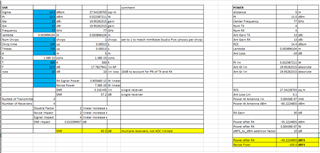
I configured the EVM for the following scenario:

My setup looks like this:

AWR2944 is located 5m far from a corner reflector with a side length of 0.1m (RCS 27.6m^2)

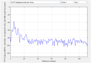
And I got this measurements:

I checked that without a corner reflector, static environment reflections at 5m range are below -55dBFS, so the signal power of -40dBFS reflects the reflector signal power accurately.

Based on the theoretical calculation, I got the same Signal power for this configuration, but the noise floor is expected to be 20dB below, that is, in place of -103dBFS, somewhere -123dBFS.

No other noise sources exist in the lab. 

I read here IWR6843AOPEVM: SNR calculation - Sensors forum - Sensors - TI E2E support forums about ~13dB Phase Noise floor level that should be added to close the link budget. But is was for IWR6843. I'm wandering whether it may be the reason for 20dB discrepancy that we observe. What is the phase noise level that should be taken into consideration for AWR2944EVM? And whether it comes from the Cristal and then may be improved by its replacement or it is the chip itself that limits FN?

Thank you,

Arie

  • Hello,

    A 20dB discrepancy seems larger than expected. Can you please share your computations which you used to arrive at this value?

    Regards,

    Adrian

  • Hi Adrian,

    sure! These are my calculus:

    Ptx = 13.5dBm (0.022Wt)

    Frf = 77GHz => Lambda=0.0039m

    GantTx = GantRx = Gant = 13dB = (20.0)

    NF = 12dB = 15.8

    Corner Reflector: side length 0.1m => RCS  = 27.6m^2

    Dist = 5m

    PI = 3.14

    Nsamp within ADC sampling time = 384

    Ndoppler = 384

    S (chirp slope) = 20.0 MHz/usec 

    Fsamp = 30MHz

    Kbolz = 1.38E-23 J/K

    Temp = 300K

    Psig @ ADC output = 10 * log10(Ptx * Gant^2 * Lambda^2 * RCS/ (4 * PI)^3 / Dist^4) = -85.2 dBm

    Nnoise @ ADC output = Kbolz * Temp * Fsamp * NF = -117.1 dBm

    Processing Gain = 10*log10(Ndoppler * Nsamp) = 51.7 dB

    SNR = Psig - Pnoise + PG = 83.5 dB

    I didn't add here the conversion from dBm to dBmFS and ignored the internal RX gain, as both of them influence the signal and the noise. Moreover, I don't know where you allocate the processing gain in the figure that you present in the PostProc tool (i.e. "Zero-velocity vs High-velocity") - in the signal part or in the noise (seems like Nsamp you allocate for the signal and Ndoppler for the noise), but at the end of the day, this is the SNR that is expected and it is 20dB better than what we measure.

    There is an issue with the high pass filter that influences static objects and could decrease their power. In the specific case it is configured for 350KHz, which influences objects located below:

    Rhigh_pass = Fhigh_pass/S * Clight/2 = 2.63m

    So, in our case with the object located at Dist=5m, it should not influence the signal power.

    Arie

  • Several additional inputs:

    1 I moved the corner reflector to 7m distance and observed the presented FFT Output signal power. I would expect the signal power change according to the rule of 40*log10(7/5)~6dB, but I observe 3-2dB difference only in the "Zero-Velocity-bin vs High-velocity-bin figure. This is a very basic indicator that something doesn't work appropriately.

    2. What is the cause for difference in the noise floor between two figures - "Zero-velocity-bin vs High-velocity-bin" and "1D FF amplitude profile (per chirp)":

    and

    I would suggest that the difference comes from the Doppler FFT processing gain, that is, 10*log10(Ndoppler), in my case Ndoppler=384, so the difference then should be ~25dB, but I don't see that. So, I don't understand correctly the difference.

  • Hello,

    Ok, thanks for the details. Let me discuss this with our systems team and get back to you.

    Regards,

    Adrian

  • Hi Adrian,

    I figured out several things:

    1. What we see at "1D FF amplitude profile (per chirp)" is indeed post Range FFT figure, scaled according to some internal dBm 2 FS scaling which doesn't fit to my calculus, but any way, this is the point. So, the processing gain at this figure relative to the ADC output is 10*log10(FFT_range).

    2. At  "Zero-velocity-bin vs High-velocity-bin" we observe additional processing gain over the number of loops, that is, in my case 64, but NOT the whole number of chirps in the frame, which is divided over 6 configurations. Consequently, the processing gain here relative to "1D FF amplitude profile (per chirp)" is 10*log10(64)=18dB, which fits to what I observe.

    3. After repetitive measurement, I do observe 6dB of difference in the signal power at 7m and 5m ranges appropriately (had to close/open mmWave Studio for that), so this question is also closed.

    4. Based on all the above, the SNR discrepancy now is 13dB and not 20dB as I mentioned earlier. May it be that 13dB comes from the Phase Noise as mentioned in  IWR6843AOPEVM: SNR calculation - Sensors forum - Sensors - TI E2E support forums ?

    5. And another critical question: suggesting that I define several configurations of the same type (as in my case I set them to 6), may I combine these chirps within the Doppler FFT to achieve an additional (maximal) processing gain?

  • Hello,

    Sorry, just a heads up. I have not had a chance to look over this yet and I will be out of office tomorrow. I will need to get back to you early next week.

    Regards,

    Adrian

  • Hi,

    just want to clarify my first (of two) question:

    We see that 2944EVM make a use of a Crystal FW, and the datasheets don't include phase noise information. I guess this means pretty low quality of a Crystal. So, if we replace this Crystal with something of a good quality, may we improve this 13dB PN noise floor or it comes from the chip itself and nothing can help.

  • Hi Arie,

    Crystal quality does affect phase noise slightly, but the dominant contributors to the noise floor are the internal VCO and synthesizer. Replacing the crystal won’t recover the full ~13dB. At best you might end up with 1-2dB improvement. 
    By the way, what package to PCB loss are you assuming in your RX calculation? And are you applying any dBFS to dBm conversion factor?

    I’ve had similar threads in the past, e2e.ti.com/.../5320007

    Regards,

    Aydin 

  • Hi Aydin, 

    thank you for the provided reference thread!

    I went through it carefully,

    I haven't used the "Package to PCB Ant Loss" at all. If I add it to my calculus, and use -10dB of dBm2FS factor, I got Psignal accurately as I measured (-39dBFS), which brings me to the gap of 7.7dB in the link budget. So, may I suggest that the gap comes from the phase noise with an internal division of 2dB for the Crystal and about 5dB for the internal chip noise floor?

    And I repeat the second critical question:  suggesting that I define several configurations of the same type (as in my case I set them to 6), may I combine these chirps within the Doppler FFT to achieve an additional (maximal) processing gain?

  • I want to clarify my second question: there is a limitation of 255 loops within Tf. But I can define several configuration groups. I my case I set then for 6. But all of them of the same type (type 0). So, can I combine all this chirps together within the Doppler FFT, as practically them are of the same type? This is crucial for our application because it provides an additional processing gain of a factor of the number of configurations I set.

  • Another relevant question: I work with DDM mode aiming to get maximum SNR. I see that using 1 or 2 Tx transmitters in mmWave Studio configuration doesn't change the number of observed channels (for 4 RX there are 4 of them) but changes the signal strength according to the beamforming rule: 20*log10(Ntx). But in DDM mode no beamforming exist: the discrepancy between transmitters is used for an angle estimation. So how do I manage to remove the beamforming and to consider the real number of channels which should be used to point cloud estimation? And.. now there are additional 6dB which are absent because when I made calculus, I used two Tx antenna and got the signal beamformed with 6dB more than it is. So totally 7.5+6=12.5 dB is absent in link budget. Please help to understand where it comes from

  • Hi Arie, 

    Thanks for confirming. Your follow up questions on the doppler FFT, loop grouping, and DDM mode beamforming behavior all fall under signal processing and SDK level implementation under the software team. I'd recommend posting those specific topics as a new thread to be addressed by the SDK software team. 

    Regards,

    Aydin 

  • Hi Aydin,

    I will do that. But there are still two questions related the link budget calculation:

    I will write here again the link budget calculus (you can correlate it with the configuration of the mmWave studio that I showed before):

    Ptx = 13.5dBm (0.022Wt)

    Frf = 77GHz => Lambda=0.0039m

    GantTx = GantRx = Gant = 13dB = (20.0)

    NF = 12dB = 15.8

    Corner Reflector: side length 0.1m => RCS  = 27.6m^2

    Ant_loss (based on your comments) = 4dB (2.51)

    Rx_gain = 30 dB

    dBm2FS = -10dB (based on the document that you provided)

    Dist = 5m

    PI = 3.14

    Nsamp (within ADC sampling time) = 384

    Nloops = 64

    Fsamp = 30MHz

    Kbolz = 1.38E-23 J/K

    Temp = 300K

    PsigFS = 10 * log10(Ptx * Gant^2 * Lambda^2 * RCS/ (4 * PI)^3 / Dist^4/ Ant_loss * 1000) + Rx_gain + dBm2FS = -39.2 dBm

    While at the mmWave studio with a single TX I get -47dBm.

    Question1: this is 8dB less than expected. So, were from may come a discrepancy here?

    Nnoise @ ADC = 10*log10(Kbolz * Temp * Fsamp * NF *1000) + Rx_gain + dBm2FS  = -67.1 dBm

    Processing Gain10*log10(Nloops * Nsamp) = 43.9 dB

    Noise @ Doppler FFT = Nnoise @ ADC - Processing Gain = -111.0 dBm

    While at the mmWave studio with a single TX I get -106dBm

    Question 2: this is 5dB more than expected. May it come from the phase noise? If yes, does it mean that 2dB comes from the Crystal and 3dB from the chip internal clock network? If no, what may be the source of inaccuracy?

  • There is an issue with the high pass filter that influences static objects and could decrease their power. In the specific case it is configured for 350KHz, which influences objects located below:

    with S (chirp slope) = 20.0 MHz/usec 

    Rhigh_pass = Fhigh_pass/S * Clight/2 = 2.63m

    So, in our case with the object located at Dist=5m, it should not influence the signal power.

  • Hi Arie,

    mmWave Studio reports in dBFS, not in dBm so not sure how you’re doing the conversion but there’s a conversion factor you’d need to take into account, please refer to the following note: e2e.ti.com/.../4555.RadarStudio_5F00_matlab_5F00_scaling.pdf

    If you were subtracting 10 dB instead, that would explain a 20 dB mismatch in your comparison.

    As for the high-pass filter, your interpretation is correct. With a slope of 20 MHz/µs and HPF at 350 kHz, the cutoff range is around 2.6 m, so a target at 5 m would not be attenuated by this filter.

    Regards,

    Aydin

  • Hi Aydin,

    thank you for your answer.

    I wrote the units incorrectly in my spread of equations, sorry for that. 

    So actually, my results were:

    Theoretical PsigFS = -39.2dBFS

    The measured value is -47dBFS

    Theoretical Noise @ Doppler FFT = -111.0dBFS

    The measured value -106dBFS

    As I wrote in my explanation, I did take into account dBm2FS = 10dB as written in the document that you provided.

    And still there are 8dB absent for the signal power and 5dB absent for the Noise.

    Totally 13 dB

    So, it doesn't speak about 20dB difference as you wrote.

    So, I kindly repeat my questions:

    Question1: signal power is 8dB less than expected. So, were from may come a discrepancy here? 

    Question 2: noise floor is 5dB more than expected. May it come from the phase noise? If yes, does it mean that 2dB comes from the Crystal and 3dB from the chip internal clock network? If no, what may be the source of inaccuracy?

  • Hi Aydin,

    I was able to improve the link budget in the lab. Probably, it may be interesting to other forum users.

    The reason that there was not enough Signal power was in the fact that I used a corner reflector with a high RCS. Such corner reflector is very direct and slight inaccuracy in the angle may cause to several dB decrease in the returned signal.

    So, we replaced it with a sphere, which has significantly lower RCS but which is much less direction dependent.

    So, currently I close the signal power with up to 1dB accuracy which may come from the measurement fluctuations. 

    I still have 4dB inaccuracy in the noise (1dB I consider for noise level measurement inaccuracy).

    Please explain me the phase noise issue: may this 4dB come from the phase noise? If yes, does it mean that 2dB comes from the Crystal and 2dB from the chip internal clock network? If no, what may be the source of inaccuracy?

  • Hello,

    Most likely the limitation on noise floor is coming from the TX-RX coupling, not the XTAL noise. You can try disabling the TX and see the idle channel noise level for impact of TX-RX coupling on the noise floor.

    Regards,

    Adrian 

  • Hi,

    I executed the TX-RX coupling measurement as you told, but not improvement in the noise floor when TX were switched off were observed.

  • Hi Arie, 

    Adrian is out of office. Let me run calculations and get back to you tomorrow.

    Regards,

    Aydin 

  • Hi Aydin,

    thanks for help. Waiting for reflection

  • Hi Arie, 

    I ran calculations with your numbers on my side and the numbers I'm getting is very close to your measurement. Please check below. 

    Regards,

    Aydin

  • Hi,

    thank you for shearing the spreadsheet.

    I see that you took 10dB for Ant loss, which is quite a lot. By my measurements it should be around 4dB for Tx-Rx of 2944EVM. So, how did you set to it 10dB?

    You also use 10dB for tx-rx phase noise. Are you sure that it is so high? What is the division between the Crystal PH and chip internal PN?

    Thanks

    Arie

  • Hi Arie, 

    The 10dB value is not just the antenna loss, it's a lumped margin that covers all practical non-idealities, TX/RX phase noise, PCB/Antenna/feed losses, and general system margin. The specific split between crystal phase noise and internal PN isn't available, but speaking with the systems team, total margin required to match lab measurements typically falls within this range. 

    Regards,

    Aydin

  • So, please clarify:

    in your spreadsheet you wrote 10dB for Ant loss and additional 10dB for phase noise.

    In your reflection, you wrote "10dB value is not just the antenna loss, it's a lumped margin that covers all practical non-idealities, TX/RX phase noise, PCB/Antenna/feed losses, and general system margin", thus I understand that the first 10dB covers all the mentioned by you losses in the system.

    Then, what is the second 10dB loss that you call "phase noise" and subtract separately in your spreadsheet? 

    Thank you,

    Arie

  • Hi Arrie, 

    Sorry for the confusion. There is no additional 10dB. It's the same value being called to use for two different calculations. 

    Regards,

    Aydin 

  • Can you please clarify with the development team how much may I improve the crystal (and subsequently) the total PH if I replace the Crystal used at 2944EVM with an external synthesizer? - the currently assembled 40MHz Crystal doesn't provide PH characteristics so I guess that it is a pretty poor one. 

  • Hi Arie,

    Improvement is unlikely to be significant. If you want to experiment, you can supply an external single ended reference as described in the datasheet. Just ensure you meet the required spec/phase noise in Table 6-6.

    Regards,

    Aydin