This thread has been locked.

If you have a related question, please click the "Ask a related question" button in the top right corner. The newly created question will be automatically linked to this question.

IWRL6432AOPEVM: User Application for UART

Part Number: IWRL6432AOPEVM
Other Parts Discussed in Thread: IWRL6432BOOST, SYSCONFIG, IWRL6432AOP, UNIFLASH

Tool/software:

Hi, 

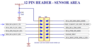
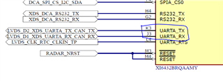
I am trying to setup UART to connect from my AOPEVM to send data to my ESP32, but I am not sure which pins on the board to use and how to set them up in the software? I cant seem to find a proper schematic/diagram that shows the correct mapping of the names of the pins on the board to the names of the pins labeled in the software. 

  • Hi Prathik,

    If you want to access UART from the device, you should be looking for RS232 pins/signals to connect to your wireless MCU. 

    If you want me to guide you through the schematic from where should the signals be brought out, please allow me some time.

    Thanks, 

    Swarnendu 

  • Hi Swarnendu, 

    thankyou and yes could you guide me through the process. I am trying to integrate UARTA so I can stream data to another microcontroller but im not sure how to do so. I have attached the screenshot of the sysconfig page. I am not really sure how the names of the pins in the sysconfig map to the physical pins upon the board. I need some kind of pin to pin connection. Could you also help me navigate how to setup some of the phyisical pins on the board as GPIO? I also have the IWRL6432BOOST and was wondering how I would do the same for that? Thankyou so much,  I have spent alot of time trying to figure this out and couldn't. I really appreciate your help. 

    Let me know if you need anymore information.

    Thanks,

    Prathik

  • Hi Prathap,

    Could you please let me know why are you not using the RS232 (UARTB) instead? For the IWRL6432AOP EVM, UARTA is not brought out in any headers. On the other hand, RS232 has been brought out to J8 which can be easily accessed. I have pasted the J8 pins and the ones you need to look at below.

    Also, the H4 and G2 are already configured as RS232, so no need of any configuration update.

    The IWRL6432AOP has 101 BGA (Ball Grid Array) balls each one of which are pin-mux'ed with multiple signals. You can take a look at the device pin-muxing table in the data sheet (https://www.ti.com/lit/ds/symlink/iwrl6432aop.pdf) table 6-1 to have a better understanding. If you configure pin J3 and K3 as UARTA, the respective physical pins will be acting as UARTA:

    Similar way you can configure any of the physical pins to the required signals.

    If you wish to integrate RS232 data to MCU, you can take out the RS232 signals from J8 and connect it to MCU. If you need to understand the UART data output format, you can refer to the below resource:

    https://dev.ti.com/tirex/content/radar_toolbox_2_20_00_05/docs/software_guides/Understanding_UART_Data_Output_Format.html#tlv-header 

    Thanks,

    Swarnendu

  • Hi,

    UARTB was already configured in the motion and presence detection OOB, so I thought it was being used for something else. Does this mean I can just use it for my own streaming of data? Do I need to add any other configuration to set the pins or is it fine just as it is for the OOB?

    (Are these the right pins)

    Also I want to send the point cloud data over UART, not the raw ADC values, so do I need to add additional code to the OOB demo? I was also wondering if there was a way to use the sensor with it running and receiving chirps just by running the code via ccs. Right now I have been flashing using UNIFLASH and then going to radar visualizer to send the configurations for the sensor. Is there a better workflow for which I can do it all within ccs if I don't care about having the visual? Also the header that I need to use for connecting the pins is too small for my wires, so I am trying to use the IWRL6432BOOST instead as it has launchpad connectivity. When I am trying to test the demo I am running into an error. I am following the same workflow to upload the code and I am following the switch settings for flashing/functioning mode but it is saying error halting. Do you have a fix?

    I am also confused on how to figure out how to map the correct pins to the correct signals within the code. For example, within the image you send the connection is xds_dca_rs232_tx on the schematic, but in ccs here are the only options. 

    I am confused on how to also configure this properly for any other GPIO pins I would want and where it is actually mapped on the board itself. I Know I asked a lot of question, and I really appreciate your help. 

    Thanks so much,

    Prathik Narsetty

  • Hi Prathik,

    Answering the questions one by one.

    RS232 in OOB demo

    Yes, by default RS232 is connected to the XDS110 debugger and through which to the USB port for PC connectivity. But from the device side, RS232 still spits out the point cloud data, as programmed in the OOB demo. So yes, you can tap out the point cloud data from RS232 without any additional updates on the device side. However, on the host side you need to have capability to match the baud rates and read the data in TLV format. I have shared the resource already in my previous answer on how to read the TLV data.

    Position of RS232 pins in J8

    That is incorrect. Please correlate the "GND" and "3.3V" pins positions on the board connector to understand what the orientation of the J8 on the board is.

    "Error halting device"

    This error can occur for several reasons. I am listing below a few of them. Please make sure you are not encountering any of them.

    1. Wrong power sequencing. This includes several possibilities such as a) Device IOs driven before the core power comes up, b) NRESET is not asserted after the power supplies are stable. Best way to mitigate this is to always assert NRESET after the SOP settings are updated and before the configuration is sent.

    2. Incorrect SOP mode. Please make sure the device is set in "functional mode" before you send the configuration.

    3. Wrong binary. Please make sure the binary/application image you are using is the correct one and not a corrupted one. Best way to check this is to take the SDK demo binary as is for a specific demo.

    4. SDK version and binary version mismatch. Please make sure you are using the visualizer from the same SDK you are taking the binary from.

    5. Wrong switch setting. Please make sure all the switch settings are as shown in the visualizer images.

    Mapping signals to the physical balls

    The EVM is developed assuming the most used functionalities and therefore the signal names are very specific. What you should be looking at while changing the functionality of a particular ball is the respective ball number. Sometimes it might be difficult to get the required functionality while the device is still sitting on the EVM. We might need to check the EVM connections in that case to verify if the updated functionality can be supported by the EVM.

    Thanks,

    Swarnendu

  • Hi, I also had a question on how to parse the binary over UART. I was able to test and see the data coming over the correct pins, but im not sure which TLV format is being used. I am using the OOB motion and presence detection with the trackerClassification high BW config. Could you guide me on how to develop a proper parsing algorithm to decode the TLV over UART and also which TLV format it is. I also want to enable the GTRACK algorithm into this and I was wondering how the TLV format changes. Thankyou so much!

  • Also another follow up, where in the code are we streaming the data out via UART for the TLV type. I want to only stream the data out if motion is detected, so I was wondering how I would set that up. Thanks!

  • Hi Prathik,

    Please find the below resource for in-detailed explanation on the data format and parsing the UART data:

    https://dev.ti.com/tirex/explore/node?node=A__AaagUFIod1NcG0sE-noAfw__radar_toolbox__1AslXXD__LATEST 

    Thanks,

    Swarnendu