


Other Parts Discussed in Thread: UNIFLASH, IWRL6432AOPEVM
Tool/software:
Hi,
I am trying to test out the OOB demo motion and presence detection on the IWRL6432BOOST and am following these steps:
1) Set board into flashing mode, then flash using UNIFLASH.
2) set Board into functioning mode, then send target configuration via radar visualizer.

this is the switch settings I am using.
But I am running into this error.

I am also confused on how to figure out how to map the correct pins to the correct signals within the code.
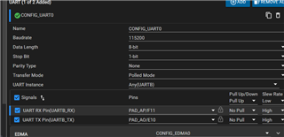
I need to configure UART, but im not sure which pins to select and where they relate to on the board itself. I want to try and use the launchpad connectivity header to also connect for some GPIO and aswell as the UART, but dont know how to map it properly. I really appreciate your help.
Thanks so much,
Prathik Narsetty


