


Tool/software:
I use TUSS4470 as it's typical diagram, except using pre-drive function with external driving power supply and MOSFET.
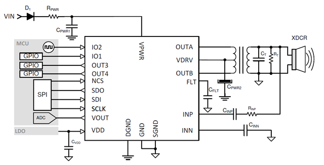
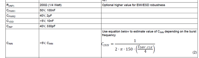
I'm confusing on the calculation of CINP, RINP and CINN, which can be described as:
1. Input voltage on INP and INN pins should be 0.5~1.3V.
2. In TUSS4470 datasheet, CINP, RINP and CINN are decided as
3. The voltage on transducer, including exciting and reflection voltage, is not considered in the calculation process.
4. Even if I know the input voltage range INP and INN, how can I decide the value of CINP, RINP and CINN, without the the related internal mechanism of TUSS4470?
Hope to get the answer, because I have broken one TUSS4470 circuit today. The situation is as below:
1. The rated peak-peak voltage of transducer is 2000V, nominal frequency is 88kHz. The transformer turn ratio is 14.
2. RINP=3k-ohm, CINP=330pF, CINN=470nF.
3. When I use the driving voltage of 24V, the peak-peak voltage apply to transducer is about 320V. The ranging process and result is within expect.
4. When I use the driving voltage of 48V, pulse applied to transducer can be captured on oscilloscope for the first time, the peak-peak voltage is about 650V. But the waveform of TUSS4470 output (Vout) goes wrong, with a light and short beep sound. When I trigger the process for the second time, exciting pulse on the transducer can not be captured any more. It seems that TUSS4470 has broken.
I think the reason must me related to the value of CINP, RINP and CINN, which should take the exciting voltage into account.
