This thread has been locked.

If you have a related question, please click the "Ask a related question" button in the top right corner. The newly created question will be automatically linked to this question.

DRV425: Recovery after large magnetic field

Part Number: DRV425
Other Parts Discussed in Thread: DRV411

Tool/software:

When I apply a large magnetic field the sensor saturated and voltage output is low. After removing the field and apply a field less than the maximum the sensor respons is normal again. However, when i apply the reversed field, with equal magnitude the sensor voltage output is high . After I remove the field the sensor stays high and it does not recover .

It only recovered when i turn of the power to the sensor or use a strong magnet close to the sensor in reverse direction .

I had an older same sensor , but although saturation amiccured it always recovered.

How can I prevent that the sensor stops measuring after a high magnetic field has been removed?

Thanks for answers.

  • Hello Victor, 

    Thank you for your post. 

    Can you provide more information on the setup and test methodology?

    What is the strength of the problematic magnetic field?

    The more information you can provide the better.

    Thank you,

    Joe

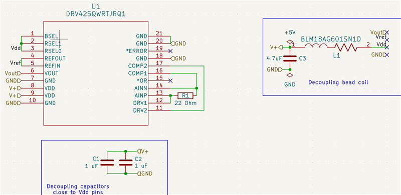
  • I made a PCB similar to the evaluation module, but with a rotated IC, so it would fit my application.

    I apply a magnetic field made with a 3 Amp current through a coil which gives about 10 mT. I put my PCB in the middle of the coil, so the magnetic field direction is parallel (or anti-parallel) to the sensors sensitivity direction. I use a shunt of 22 Ohm, so my sensitivity is 0.93 mT/V and the maximum field is 2 mT.

    When I apply the field in one direction, the output signal reduces from 2.5 V to below 0.5 V. When I turn the current off, the sensor’s output is returned to 2.5 V and it responses in the correct way on further (much smaller) changes of the magnetic field. As long as I do not change the set-up, i.e. as long as the direction of the current does not change, I can turn the current on and off, without the sensor losing its accuracy in the measurements when the current is off.

    However, when I reverse the current in the coil, i.e. reversing the direction (but not the maximum strength) of the magnetic field on the sensor, the situation is different. When I turn on the current the sensors output becomes close to 5 V, which is of course logical, but when I turn off the current, the sensor output remains 5 V and it does not react on small changes in the magnetic field any more. 

    The sensor is not broken, because when I turn the power off and on again, the sensor starts operating as it should. For the sensor I have this is very reproducible.

    Without removing the power it is also possible to recover normal operation when I use a permanent magnet with a very large (>50mT) field applied temporary on the sensor in a reversed direction of the field compared to the field that clipped in the 5 V position.

    The strange think is that I did not have this problem with on earlier version of the drv425.


  • Hello Victor, 

    Thank you for the clarification. 

    I believe your issue is that you are close if not exceeding the maximum magnetic field of +/-2mT.

    The DRV425's measurement range is determined by the amount of current that it is able to drive. 

    I would suggest taking a look at this app note where the DRV411 is being used to measure larger magnetic fields: https://www.ti.com/lit/ug/tidu820/tidu820.pdf 

    The way this is achieved is by adding external compensation coil drive capability. 

    This may be one way that you can address your issue. 

    I hope this helps, 

    Joe

  • It does not help me to use a different sensor as I need it to measure very small magnetic fields directly after the current through the coil has been switched off. A Hall sensor cannot do that.

    I could add an external compensation coil drive, but that adds to the complexity of my system that is not warranted, because I only need to measure very small magnetic fields and not the large fields.

    I understand that I am out of the sensor's range. But that is not the question. The question is about recovery of the sensor when an over-range occured. It does not recover if the overrange is in one direction, but it does when it is in the other. And the acutal question is why this occurs now, while with previous ones, this was never an issue.

  • Hello Victor, 

    I was suggesting to potentially add this external drive capability to the DRV425. I was not suggesting to switch to a hall based device for your application. But I understand that this is not an option for you. Would you say this is more stress testing with these stronger magnetic fields? 

    We have had customers apply 1T and then remove the field, bringing the device back out of saturation. There is also a recovery time and hysteresis window for the saturation. The recovery time can be tens to hundreds of µS and the hysteresis is typically 1.4µT. 

    I do have more questions about your use case:

    1. For my knowledge and understanding can you provide your results from the DRV425 system parameter calculator?
    2. Have you also been probing the ERROR pin during this reverse condition? 
    3. In your system is it possible that the DRV425 is saturated when it is not powered on? 
      1. We have tested a saturated DRV425 with no supply voltage and when powered on, it will remain saturated at the positive rail regardless of primary current direction. 
    4. If you are able, can you provide an image of your DRV425 setup with your coil?
    5. Do you have fast magnetic field transients in your system?

    To my knowledge, there has not been a design change for this device. 

    Best Regards, 

    Joe

  • To answer your questions:

    1. see below
    2. no
    3. When I turn the sensor on and off the sensor behaves as it should, only after a magnetic field pulse of 10 ms (block shape) and 50 mT in one direction the sensor stays clipped.
    4. see below
    5. Yes, the magetic field switches of in less than 0.1 ms.

    Schematic:

    Schematic

    PCB:

    PCB

    Photo setup (sensor removed from inside coil for photo):

    Setup

    Spreadsheet:

    DRV425 - System Parameter Calculator_01072025.xlsx

  • Hi Victor, 

    Thank you for this information. 

    I am going to discuss this with our lead engineer who may have seen this similar issue, as I have not.

    He is OOO this week for the 4th of July US holiday but I will provide you with an update on 7/7. 

    In the meantime do you have the ability to probe the ERROR pin during your testing?

    I will also use this information for the discussion. 

    Best Regards, 

    Joe

  • Hi Joe,

    I repaced R1, (was 22 Ohm) by 100 Ohm and 33 Ohm and the problem is not occuring in these cases.

    When I use 26 Ohm, the problem remains....

    Greetz,

    Victor

  • Hello Victor,

    This is interesting and I have not seen or heard of anything like this.  Can you verify something for me.  Is the current on R1 match the output voltage? 

  • Dear Javier,

    I used a different sensor now, because I killed the other one. Now the effect also occurs for 33 Ohm as R1.

    I measured the voltage over the resistance of 33 Ohm. 

    Without strong field I measure about 20 mV.

    During the strong magnetic field in a direction parallel to the sensing direction I measure a voltage of +1.236 V; when I switch off the strong magetic field it returns to 42 mV. As long as I do not change the sign of the magnetic field, this is very reproducable.

    When I reverse the direction of the magnetic field (i.e. change the sign) I measure -1.248 V during the strong magnetic field and -1.229 V after switching off the strong magnetic field. This value does not change anymore. I can only reset the sensor by turning th  power supply off and on again or by using a magnetic field of a magnet close to the sensor, when the direction of the field of the magnet is in the same direction as the strong magnetic field which caused the freaze of the sensor. In the oppostie direction, the sensor can not be reset.

    When I do the same measurements again with a resistance of 101 Ohm, I get the following results:

    Without strong field I measure about 35 mV.

    During the strong magnetic field in a direction parallel to the sensing direction I measure a voltage of +2.51 V; when I switch off the strong magetic field it returns to 140 mV. As long as I do not change the sign of the magnetic field, this is very reproducable.

    When I reverse the direction of the magnetic field (i.e. change the sign) I measure -2.54 V during the strong magnetic field and -38.6 mV after switching off the strong magnetic field. Now this is also reproducable, and all seesm to be normal.

    Greetz,

    Victor

  • Victor,

    This is very strange and I do not understand what could be causing this issue.  Can you replace the ferrite bead with a 0Ω resistor?  Two things that this may be is the transient on the field could cause a large current requirement from the DRV425 and limiting that may cause the issue.  The change is resistance may change the response enough that it does not cause the issue.  Another is the spike on the ferrite bead may cause a change in the field, I think this is less likely but I am not sure if the ferrite bead can get magnetized.  The reason I doubt this is that it recovers after you reset.

    Please let me know if this fixes the issue as if it does this may come up again.  The reason I asked for the measurement on Rshunt is removing the output amplifier from the issue.

    Regards,

    Javier

  • Dear Javier,

    This is exactly what I have done first, bit it did not make any difference.

    However, what I think is strange, is that the max/min voltage over R1 (i.e. the shunt resistor) is only +/-1.24 V when the sensor is saturated for R1=33 Ohm, while it is +/- 2.5 V when R1 = 100 Ohm. This shows that the maximum current with R1=33 Ohm is only 37 mA. I understand that as the maximum supply voltage is 5 V and the resistor of the compensating coil is 100 Ohm, 33/133*5V=1.24V. 

    I suspect that the feedback control needs to drive the GMR into saturation again, but the feedback control loop does not recognize it, as the voltage over the shunt only becomes +/-1.24 V. Hence, when you use a magnet to drive the GMR into saturation (works only when using the correct magnetic field sign, with a field produced by placing a strong magnet close the the sensor i.e. larger than the one that cause the clipping of the sensor) the feedback control is somehow reset. I focus on the "feeback control" as the sensor also restarts working when you put off and on the power, hence it can not be an intrinsic issue of the GMR.

    Greetings,

    Victor

  • Victor,

    The DRV425 does not have a GMR but rather some magnetic material that is driven internally in and out of saturation in both directions.  Normally this is 50% duty cycle in normal operation and the feedback keeps it in that mode by applying the correct compensation current to balance the saturation in both directions.  When the feedback cannot compensate enough for the magnetic field this basically keeps the device in saturation mode in one directions.  Normally when the saturating magnetic field is removed the device continues to attempt to saturate the probe material in both directions and would return to operate back to normal.  The case where the magnetic field is removed I would assume the feedback would then drop to zero at the field would be over compensated.  Do you do this both slow and fast transients of the magnetic field.  I am wondering if the saturation point goes in the wrong direction.  I do not know what could cause this as I have done this to our devices before as well and they recovered without power on or off.

    Also the device having a larger resistor would limit the current on the compensation coil so it should saturate at a lower magnetic field, but you are seeing better results.

    Regards,

    Javier

  • So the current through the shunt is just some offset for the complete oscillation of the magnetic field in the sensor?

    Anyhow, as I do not have a clue about the actual feedback system, I can not contribute more to the search for the reason of the mall function.

    I just have to increase the resistance value and search for different solutions when I need to measure a higher field.

    Greetz,

    Victor

  • Hello Victor,

    So the current through the shunt is just some offset for the complete oscillation of the magnetic field in the sensor?

    This is correct and that current is what translates to magnetic field at the sensor.  Once you limit the current going through the compensation coil is met due to the Rshunt, compensation resistance (100Ω)  and voltage supply then the flux-gate gets saturated. 

    The reason I am confused is higher Rshunt makes out flux-gate get saturated at less magnetic field due to limiting the shunt.  This to me means we may be having a transient issue that is different response time with larger Rshunts.

    I would almost want to recommend a parallel capacitor on Rshunt  to speed up the response.  Or a capacitor to GND from Comp1 pin to slow it down.  I do not know which would would be better.  I will think about this and see if I can explain it but at the moment I am guessing .

    Regards,

    Javier