


Tool/software:
Hello TI team,
I am currently working with the AWR1843AOP IC and have successfully flashed the MRR (Medium Range Radar) application from the Radar Toolbox (radar_toolbox_2_20_00_05). I have a question regarding the coordinate frame interpretation based on the physical orientation of the radar module.
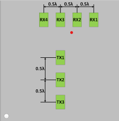
As per the documentation (obstacle_detection_aop_users_guide.html), Scenario 1 :physical orientation of the AWR1843AOPEVM should be as per below and the chip the antenna placement as per below
in this case packet data x cordinates means ( distance along lateral axis) ,Y cordintates (Distance along longitudinal) and Z (Distance along height axis) 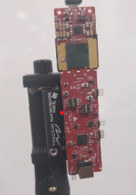
Scenario 2: if i mount the AWR1843AOPEVM as below and antenna placed as per below pic
Questions :
-
Is my understanding of the X, Y, and Z coordinates correct in the described scenarios 1?
-
In Scenario 2, what is the interpretation of the X, Y, and Z coordinates provided in the radar packet data with respect to the radar AWR1843AOPEVM?
-
Do these coordinates retain the same meaning as in Scenario 1, or do they change based on the physical orientation of the radar module?
-
