This thread has been locked.

If you have a related question, please click the "Ask a related question" button in the top right corner. The newly created question will be automatically linked to this question.

TMCS1101: Wrong output value after power on for a few minutes

Part Number: TMCS1101

Tool/software:

Hello,

We are using a TMCS1101A3B sensor on our custom board powered via AC, here’s the schematic of the current sensing part:

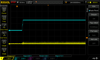
Once every like twenty power cycles, the sensor outputs a very low voltage on Vout instead of 0.5×Vs as it normally does. After a few minutes, it comes back to normal. We don’t have any load during this whole time so we should just be getting the middle value.

On one of our board, I measured 43 mV after powering up the board. Then it jumped back to 1 690 mV (0.5×Vs) after about 2 minutes. It may take a longer or shorter amount of time to come back to normal values (I observed roughly between 30s and 10 minutes).

Do you please have any idea about what could be causing such an initialization issue?

Thanks, best regards.

  • Gilles,

    This certainly does not seem like expected behavior for the device. Is it possible to get a scope shot monitoring the output, Vs, and the input current on a scope during such an event?

  • Thanks for your reply. Here are the measurements we did, with Vs in blue, Vout in yellow, and no load at all. Vout is measured on C34 after our RC filter as it seems we couldn’t reproduce the issue when the probe was directly on Vout…

    Power on with the glitch for about 350 ms before it shoots back to normal value (the noise on Vs was because of the measurement setup, I fixed it in the next screenshots, the power signal is clean and doesn’t have an impact on the glitch):

    Another glitch where it came back to normal after a longer time (about 2 minutes):

    Here’s when it’s coming back:

    Here’s a zoomed in portion of Vs in AC mode (it measures at 3.28 V otherwise):

  • Gilles,

    Thanks for the question and using the E2E forum.

    Due to the U.S. holiday on July 4, we are currently out of the office. Someone will reply when we return on Monday, July 7.

    Thank you for your patience.

  • Thanks for the reply.

    For information, we have the same issue even when we completely remove the RC filter and have Vout directly go to our ADC input.

  • Gilles, 

    Understood. You say "roughly 20 power cycles," During these tests, are you rapidly power cycling the device on and off, or is it simply a random occurrence?

  • It happens in both cases: I’m toggling the device on and off about every 5 seconds to try to reproduce it quickly, but it also occurred after a few hours on the first power-on.

  • Gilles,

    Understood. Is this reproducible on other boards or is this bound to a single device? 

  • Yes it does happen on every board.

  • Replacing C34 by a 10kΩ pull-down and shunting R30 yields the same results.

  • Hi Gilles,

    You initially said that the error was not seen when you probe directly on the Vout pin, but did occur when you probe after the RC filter. Now with RC filter removed the error occurs still. If you disconnect the ADC input does the error still occur? I wonder if the ADC is pulling the signal down randomly.

    Can you disconnect R30 and probe on Vout to see if the glitch occurs? Also probe the input of the ADC with C34 populated to see if what is going on there.

    Best,

    Holly

  • Hi Holly,

    Thanks for the reply. It’s still harder to reproduce the issue with the scope’s probe on, but I managed to do it while having R30 and C34 disconnected, which means there’s nothing connected on Vout other than the scope’s probe:

    The signal came back to a normal neutral level after about 30 seconds:

    The same glitch with the scope in “High resolution” acquisition mode:

    It’s still quite easier to reproduce the issue when the scope’s probe is off the Vout pin, and when it’s at the wrong “glitch” level, putting back the probe on Vout makes the signal come back to normal generally after about 5 seconds.

    Regarding measurements on the ADC input with C34 populated, those are the ones I uploaded above on the 4th, which show the same glitch and same levels, only filtered.

  • Are you driving a SAR ADC?
    I would recommend going through this AppNote. It has lots of helpful information including details about the need for a charge bucket which I think might be what we need in this situation.

    Please go through it and let me know if you have any questions.

    BR,

    Holly

  • The datasheet of our MCU isn’t 100 % clear on that, but I found this in an application note: “The EFR32 Wireless Gecko Series 2 IADC is an intermediate architecture combining techniques from both Successive Approximation Register (SAR) and Delta-Sigma style converters.”

    Thanks for the application note, but either way, the measurements that I have sent above were done “while having R30 and C34 disconnected, which means there’s nothing connected on Vout other than the scope’s probe”. Hence I am not sure adding a charge bucket (which is basically an RC filter with an additional resistor to ground) after the Vout pin would make the component not glitch out with its initialization level, as this happens whether or not an RC filter is present.

    Best regards.

  • Hi Gilles,

    Can you depopulate C35 (the capacitor on the NC pin 6)?

    This is a rather large cap and while we can tolerate a capacitive connection to ground this is quite large. Removing this might clean up that oscillation we're seeing in the first photo you just sent.

  • Hi Holly,

    Same results with C35 unpopulated: the glitch appeared after 5 power on:

    I have also tried with pin 6 shunted to GND, same issue after 10 power on:

    It’s really frustrating, we cannot seem to find a way to alter this behavior, neither positively nor negatively…

  • Hi Gilles,

    I apologize for my delay. I agree this behavior is not making sense. I have discussed with a colleague and I think it could be good to go back to the basics for a sanity check.

    -Check to make sure there are no cold solder joints

    -Measure the supply voltage from the VS pin on device to the GND pin of device so we can ensure we are seeing the same voltage the DUT is seeing

    The first photo you sent had a noisy supply and you mentioned that this was a measurement setup issue. What changed in the setup to make the signal look cleaner?

  • Hi Holly,

    Doesn’t look like there is any cold solder joint, the issue happens on all of our boards, whether they are hand-soldered or professionally assembled.

    All the Vs measurements are done with the probe on the component’s GND and Vs pins directly. On the first screenshot the GND actually wasn’t probed on the component itself, it was a bit further away which caused the noise. The supply looks very clean in all the other measurements done.

  • Hello Gilles,

    This has stumped me as well as Holly asked about this.  We will pull our team together and brainstorm on what this could be.  We will give you a reply tomorrow or Monday.  As a few people are off and return on Monday.

    Regards,

    Javier

  • Hello Javier,

    Many thanks, we appreciate this! We tried quite a few different things (as discussed above): checking supply’s filtering and noise, swapping components, disconnecting pins, and more, but still observe the same behavior that is not happening every time (whatever the time interval is between the power cycles).

    Have a nice day, best regards.

  • Hi Gilles,

    We have ordered parts and are going to work to recreate this issue in our lab.

    1. What is the slew rate of your power supply?

    2. Are there any external magnetic fields present?

    3. Do you have any order information. What is the lot# of these devices? When did you order them and from where?

    Best,

    Holly

  • Hi Holly,

    Thanks for your involvement on this issue!

    1. Here’s a screenshot of the device’s power-on, again with Vs in blue and Vout in yellow, so there’s a total rise time of the power supply of about 7.5 ms. 

    2. Not that I know of. The issue happens in the same way on two variants of our board: one with two relays (but that are never driven when encountering the issue), one with a MOS and Triac instead of the relays (same operation: not driven at power on).

    3. We lack some tracking data for these boards unfortunately, although we do know they probably come from one of those orders on the TI Store: T04759898, T04574422, T04571269. Marking on the ICs are `M01A3B 29K M006`.

    Best regards.

  • Hi Gilles,

    Thank you for this information. The parts we ordered have not arrive yet. I will give you an update on Friday to let you know our progress.

    Best,

    Holly

  • Hi Holly,

    Do you please have any information for us yet?

    Best.

  • Hi Gilles,

    We have parts, unfortunately they have not come from the same lot. We are trying to find some parts from the same lot.

    However, I have tested the devices I have and have not been able to reproduce the issue. I continuously cycle the power on and off (3.3V) and monitor the output to see if it ever goes low or if there is a long delay and I have seen none. We consistently get a startup time of ~25ms.

    Best,

    Holly

  • Hi Holly,

    Thanks for your update and experiments. Could we eventually send you a board of ours that present the issue, so that you can further investigate in a known and reproducible environment?

    Best.

  • Hi Gilles,

    You can ship us your board, but it is a difficult thing for us to be able to ship it back to you. You could also ship us parts off of your board (those are easier for us to send back).

    We plan to order samples and send you some and we keep some that way we are both testing devices from the same lot. I will send you a friend request and we can private message about the information I will need from you for this to work.

    Best,

    Holly