This thread has been locked.

If you have a related question, please click the "Ask a related question" button in the top right corner. The newly created question will be automatically linked to this question.

FDC1004-Q1: SO#396979 FDC1004QDGSRQ1 operation problem

Part Number: FDC1004-Q1
Other Parts Discussed in Thread: FDC1004, LP2950

Tool/software:

Dear Technical Support,

Good day!

Please verify for FDC1004QDGSRQ1 and provide guidance for proper operation.
Or confirm if can be considered as defective ?
     
      INV#85247807 595-FDC1004QDGSRQ1 ALL 10PCS (Mouser PO# 029-Y9481)

Invoice

Shipped

Cust #

Cust Name

Customer PO

Part Number

Qty Shipped

Issue COO

Date Code

Trans Date Code

Lot Code

Supplier
PO

Supplier Name

Received

Picked

Issue IBN

Mouser PO

Rec IBN

DC Required

DC Preferred

Mini Reel

85247807

2025-06-30

61DB5D6

BUNPEI DOKO

36186123

595-FDC1004QDGSRQ1

10

MY

2145 

2145 

1325321EM1 

5951

Texas Instruments

2021-12-29

2025-06-30

41JDOX

029-Y9481

8ZIEDN

NO

NO

NO


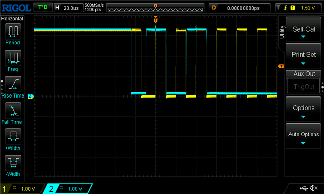
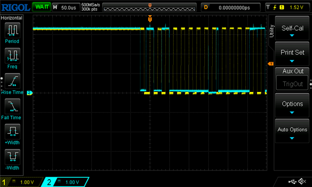
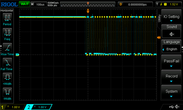
      We have confirmed the operation of FDC1004 under the following conditions,
      but even after starting the measurement, bit 15 (measurement completion
      flag) of the status register does not stand and the measurement operation
      cannot be started.
     
      //Operation conditions//
      _Power supply: stable 3.3V supply by LP2950 (3.3V during operation has
      been confirmed with a tester)
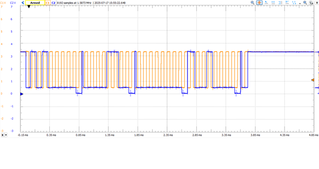
      _Microcontroller: Arduino Uno (I2C signal has been confirmed via logic
      level converter or direct 3.3V connection)
      _I2C clock: 50kHz
      _Pull-up resistor: 3.3V to 4.7k_ (both SDA/SCL)
      _Between OUT and GND: 0.1_F + 1_F decoupling capacitor installed
      _CIN1: metal electrode connected
      _GND: continuity between microcontroller and FDC1004 GND confirmed with a
      tester
      //What we tried//
      _I2C scanner successfully detected address 0x50 Soft reset, measurement
      setting, and measurement start command were all successfully sent by
      Wire.endTransmission() (return value 0)
      _Tried both single-shot measurement mode and continuous measurement mode
      _The status register value always remains 0, and the measurement
      completion flag is not raised
      _Same results with multiple FDC1004s Result
      //Consultation details//
      As described above, we believe that the power supply, wiring, and I2C
      communication conditions are correct, but we are unable to enter the
      measurement operation.
      In this case, is it correct to assume that there is a possibility of an
      initial defect or defective operation?
      If necessary, we will send you the wiring diagram, test code, logs, etc.
      Thank you in advance.

Regards,
Manuel

  • Hello Manuel,

    I think it would be good to see some scope captures to see if anything peculiar is happening during the communication.  I would start with seeing if what you attempt to write is what you actually read from the registers you tried to configure.

  • Dear Patrick,

    Thanks for the verification and guidance.


    Posting below received additional update if can help.


      Status Details


          - There is a normal response to the I2C address (0x50).

          - Writing to and reading from the MEAS1 setting register (0x08) can be

          performed normally and the values are reflected.

          - The measurement start command (0x10 written to 0x0C) can also be

          transmitted normally, and Wire.endTransmission() always returns 0.

          - After starting measurement, checking the FDC config register (0x0C), the

          measurement start/completion bits (bit4, bit7) are not set at all.

          - After soft reset (writing 0x80 to 0x0C), the status remains the same and

          measurement cannot be started.

          - The power supply is stable at 3.3V (3.323V) and a decoupling capacitor

          (0.1F + 1F) is already installed between VDD and GND.

          - The I2C clock can be set to 50kHz or 25kHz in addition to the standard

          100kHz.


          Summary of confirmed contents


          - I2C communication itself is normal.

          - Measurement setting and start commands are being sent.

          - The measurement engine does not operate at all and the measurement start

          flag is not raised.


    Regards,
    Manuel

  • Hello Manuel,

    Thank you for providing those additional details.  Seems as though the read function is working as intended.  However, I suspect there may be an issue with the write function.  If you provide some oscilloscope captures, I think it will help provide some additional insight into what might be going wrong with the transmission.

  • Dear Patrick,

    Thanks for the verification. Noted possible write function issue.

    Will share the oscilloscope capture once received

    Regards,
    Manuel

  • Dear Patrick,

    Please refer to below and attached update.

    Waveforms of I2C communication of FDC1004 were acquired using an

    oscilloscope and are attached.

    - The attached images were acquired with time scales of 100_s, 50_s, and

    20_s, respectively.

    - CH1 (yellow) = SCL (SCL pin of FDC1004)

    - CH2 (blue) = SDA (SDA pin of FDC1004)

    Communication waveform is observed, but ACK response from FDC1004 may not

    have been obtained and measurement cannot be started.

    We would appreciate it if you could check if there is any problem with the

    waveform and if the FDC1004 is responding correctly.

    Regards,
    Manuel

  • Thanks Manuel,

    I need some time to look at those more closely and possibly compare against what I can see on the bench.  I will try to get back to you tomorrow afternoon.

  • Thanks Patrick, noted that. Please share once verified.

    Or advise if there are other detail needed.

  • Hey Manuel,

    You could be violating a timing specification, you might want to look at various parts of your communication to verify none of the specification in table 5.7 of the datasheet are violated.

    Per my bench tests, it does look like I am able to write 0x0090 to register 0x0C. Below is what my write looked like:

  • Dear Patrick,

    Thanks for the verification and guidance.

    Cannot locate for Table 5.7, that should be 5.7 I 2C Interface Timing portion, right ?

    Have a great weekend.

    Regards,
    Manuel

  • Hi Manuel,

    Patrick is out today, but he should be able to take a look when he is back tomorrow.

    Regards,

    Mekre

  • Dear Patrick,

    Thanks a lot.

    ABOVE SOLVED CUSTOMERS PROBLEM. THANK YOU, CLOSING


    Regards,
    Manuel