IWRL6432AOPEVM: After flashing IWRL6432AOPEVM works but after power reboot it does not work as expected.

Part Number: IWRL6432AOPEVM
Other Parts Discussed in Thread: SYSCONFIG,

Tool/software:

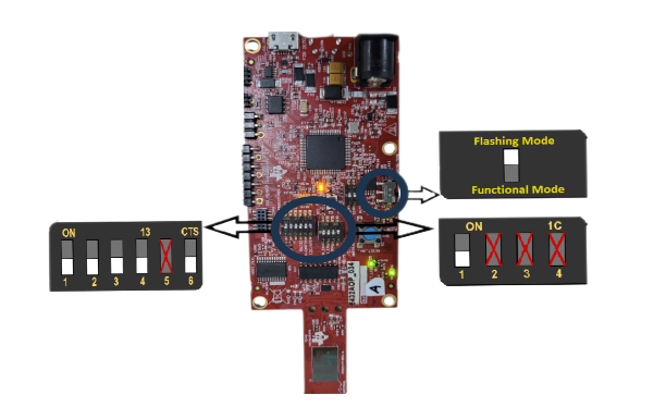
Hi Team, Currently I am working on IWRL6432AOPEVM board, I have configured the HCC ( configuration for radar sensor in the App image itself) with Quick Evaluation feature from sysConfig and updating the mmw_cli.c file. I have also configured the Power section in sysConfig to wake it up from deep sleep using SYNCIN_IO (J2 on on board) by pulling this J2 pin with my host MCU. After building the project in CCS I flashed it using CCS as well but I was not getting the radar data on uart of my host MCU. But to my surprise when I flashed the same image using visualizer(from MM_WAVE_L_SDK_05_05_03_00  tools > web page) I started getting the data. Everything seemed to be working until I did a power reboot. After Power reboot I was not getting the radar frame data although I was able to drive the J2 pin because the LED connected on the same pin was getting ON and OFF, I did the flashing again with the visualizer same as previous and again I started receiving data after each 5 minutes  by driving the SYNCIN_IO once in 5 minutes. My queries are as following.

1. Why flash with CCS IDE does not work same as it works after flashing with visualizer dashboard webpage's flash utility.

2. Why it does not work the same after power reboot and works fine after re flashing. Ideally I expect everything to work fine when all the config are the part of flashed app image and it's operation should not affect on power reboots.

3. Does the radar sensor send only one frame data after coming out of deep sleep or it keeps on sending until going to deep sleep again? If it sends only one frame after coming from LPDS what can be done to receive few more frame data?

Thank You.

  • Hi there,

    Please allow me a couple of days to get back to you.

    Thanks,

    Swarnendu

  • Hi,

    I don't think you can operate with low power mode enabled in CCS IDE. Where does the code gets halted in this situation? Is it possible to share the configuration you are using and the sysconfig file parameters?

    Regards,

    Sharan

  • Hi Sharan, even if I can not operate with low power in CCS IDE I do not have problems if I can flash the application with visualizer(given in the sdk) dashboard tool and run the application, the main problem I am facing is that after flashing from visualizer why the code runs fine just after the flash and not after the next power reboot.

    In case of CCS IDE are you asking about the halt when using CCS IDE to run the code in debug mode?

    I have shared a text file with copied contents of file example.syscfg from the Generated File section, apart from this what are the other configuration data you need?

    Thank You

    /**
     * These arguments were used when this file was generated. They will be automatically applied on subsequent loads
     * via the GUI or CLI. Run CLI with '--help' for additional information on how to override these arguments.
     * @cliArgs --device "XWRL64XX" --package "AOP" --part "Default" --context "m4fss0-0" --product "MMWAVE-L-SDK@05.05.03"
     * @versions {"tool":"1.20.0+3587"}
     */
    scripting.excludeFromBuild("ti_cli_mmwave_demo_config.h");
    
    /**
     * Import the modules used in this configuration.
     */
    const flash      = scripting.addModule("/board/flash/flash", {}, false);
    const flash1     = flash.addInstance();
    const ina        = scripting.addModule("/board/ina/ina", {}, false);
    const ina1       = ina.addInstance();
    const ina2       = ina.addInstance();
    const ina3       = ina.addInstance();
    const mpd_demo   = scripting.addModule("/demo/mpd_demo/mpd_demo", {}, false);
    const mpd_demo1  = mpd_demo.addInstance();
    const edma       = scripting.addModule("/drivers/edma/edma", {}, false);
    const edma1      = edma.addInstance();
    const edma2      = edma.addInstance();
    const hwa        = scripting.addModule("/drivers/hwa/hwa", {}, false);
    const hwa1       = hwa.addInstance();
    const i2c        = scripting.addModule("/drivers/i2c/i2c", {}, false);
    const i2c1       = i2c.addInstance();
    const power      = scripting.addModule("/drivers/power/power", {}, false);
    const power1     = power.addInstance();
    const uart       = scripting.addModule("/drivers/uart/uart", {}, false);
    const uart1      = uart.addInstance();
    const mpu_armv7  = scripting.addModule("/kernel/dpl/mpu_armv7", {}, false);
    const mpu_armv71 = mpu_armv7.addInstance();
    const mpu_armv72 = mpu_armv7.addInstance();
    const mpu_armv73 = mpu_armv7.addInstance();
    const mpu_armv74 = mpu_armv7.addInstance();
    const timer      = scripting.addModule("/kernel/dpl/timer", {}, false);
    const timer1     = timer.addInstance();
    
    /**
     * Write custom configuration values to the imported modules.
     */
    flash1.$name                  = "CONFIG_FLASH0";
    flash1.peripheralDriver.$name = "CONFIG_QSPI0";
    
    ina1.$name = "CONFIG_INA0";
    
    ina2.$name            = "CONFIG_INA1";
    ina2.I2CTargetAddress = "0x41";
    
    ina3.$name            = "CONFIG_INA2";
    ina3.I2CTargetAddress = "0x44";
    ina3.shuntRes         = 20;
    
    mpd_demo1.$name       = "CONFIG_MPD_DEMO0";
    mpd_demo1.QUICK_START = "1";
    
    edma2.$name                        = "CONFIG_EDMA1";
    edma2.edmaRmDmaCh[0].$name         = "CONFIG_EDMA_RM5";
    edma2.edmaRmQdmaCh[0].$name        = "CONFIG_EDMA_RM6";
    edma2.edmaRmTcc[0].$name           = "CONFIG_EDMA_RM7";
    edma2.edmaRmParam[0].$name         = "CONFIG_EDMA_RM8";
    edma2.edmaRmReservedDmaCh[0].$name = "CONFIG_EDMA_RM9";
    
    hwa1.$name = "CONFIG_HWA0";
    
    i2c1.$name = "CONFIG_I2C0";
    
    power1.$name                      = "CONFIG_POWER0";
    power1.enterLPDSHookFunction      = "power_LPDSentryhook";
    power1.resumeLPDSHookFunction     = "power_LPDSresumehook";
    power1.thresholdForSleep          = 99999999;
    power1.totalLatencyForSleep       = 99999999;
    power1.ramRetentionMaskLPDS       = ["APP_PD_SRAM_CLUSTER_1","APP_PD_SRAM_CLUSTER_2","APP_PD_SRAM_CLUSTER_3","APP_PD_SRAM_CLUSTER_4","APP_PD_SRAM_CLUSTER_5","APP_PD_SRAM_CLUSTER_6","FEC_PD_SRAM_CLUSTER_1"];
    power1.enteridle3HookFunction     = "power_idle3entryhook";
    power1.resumeidle3HookFunction    = "power_idle3resumehook";
    power1.wakeupGPIOEdgeLPDS         = "RISE_EDGE";
    power1.enableGPIOSYNCINWakeupLPDS = true;
    power1.selectGpioSyncioLPDS       = "POWER_SYNCIN_IO_WAKEUP_LPDS";
    power1.wakeupSYNCIOEdgeLPDS       = "RISE_EDGE";
    power1.parkPins.$name             = "drivers_power_v0_power_v0_pins0";
    power1.parkPins.changeAllPins     = "PARK";
    power1.parkPins.PAD_AQ            = "DONT_PARK";
    power1.parkPins.PAD_AR            = "DONT_PARK";
    power1.parkPins.PAD_AS            = "DONT_PARK";
    power1.parkPins.PAD_AT            = "DONT_PARK";
    power1.parkPins.PAD_AV            = "DONT_PARK";
    power1.syncio.$name               = "CONFIG_SYNCIN0";
    power1.syncio.SYNC_IN.IN.$assign  = "PAD_AV";
    
    uart1.$name           = "CONFIG_UART0";
    uart1.intrEnable      = "DISABLE";
    uart1.UART.RX.$assign = "PAD_AP";
    uart1.UART.TX.$assign = "PAD_AO";
    
    edma1.$name                        = "CONFIG_EDMA0";
    uart1.edmaConfig                   = edma1;
    flash1.peripheralDriver.edmaConfig = edma1;
    edma1.instance                     = "EDMA_APPSS_B";
    edma1.edmaRmDmaCh[0].$name         = "CONFIG_EDMA_RM0";
    edma1.edmaRmQdmaCh[0].$name        = "CONFIG_EDMA_RM1";
    edma1.edmaRmTcc[0].$name           = "CONFIG_EDMA_RM2";
    edma1.edmaRmParam[0].$name         = "CONFIG_EDMA_RM3";
    edma1.edmaRmReservedDmaCh[0].$name = "CONFIG_EDMA_RM4";
    
    mpu_armv71.$name        = "CONFIG_MPU_REGION0";
    mpu_armv71.attributes   = "Device";
    mpu_armv71.allowExecute = false;
    
    mpu_armv72.$name    = "CONFIG_MPU_REGION1";
    mpu_armv72.baseAddr = 0x400000;
    mpu_armv72.size     = 19;
    
    mpu_armv73.$name    = "CONFIG_MPU_REGION2";
    mpu_armv73.baseAddr = 0x22400000;
    mpu_armv73.size     = 19;
    
    mpu_armv74.$name             = "CONFIG_MPU_REGION3";
    mpu_armv74.accessPermissions = "Supervisor RD, User RD";
    mpu_armv74.size              = 18;
    
    timer1.$name         = "CONFIG_TIMER0";
    timer1.timerCallback = "timerCallbackDefcfg";
    
    /**
     * Pinmux solution for unlocked pins/peripherals. This ensures that minor changes to the automatic solver in a future
     * version of the tool will not impact the pinmux you originally saw.  These lines can be completely deleted in order to
     * re-solve from scratch.
     */
    flash1.peripheralDriver.QSPI.$suggestSolution      = "QSPI0";
    flash1.peripheralDriver.QSPI.DOUT.$suggestSolution = "PAD_AC";
    flash1.peripheralDriver.QSPI.DIN.$suggestSolution  = "PAD_AD";
    flash1.peripheralDriver.QSPI.DIN0.$suggestSolution = "PAD_AE";
    flash1.peripheralDriver.QSPI.DIN1.$suggestSolution = "PAD_AF";
    flash1.peripheralDriver.QSPI.CLK.$suggestSolution  = "PAD_AA";
    flash1.peripheralDriver.QSPI.CS.$suggestSolution   = "PAD_AB";
    i2c1.I2C.$suggestSolution                          = "I2C0";
    i2c1.I2C.SCL.$suggestSolution                      = "PAD_AG";
    i2c1.I2C.SDA.$suggestSolution                      = "PAD_AH";
    power1.syncio.SYNC_IN.$suggestSolution             = "SYNC_IN0";
    uart1.UART.$suggestSolution                        = "UARTB";
    timer1.APPSS_RTI.$suggestSolution 

  • Hi Sharan, any update on the above query? 

  • Hi,

    Have you made any changes in the FW? If so, could you list them out?
    Ideally, you are required to flash only once, then the application should work as expected for every power reboot in functional mode.

  • Hi Sharan, I did change in the PresenceDetect.cfg file for baud rate, perhaps 1 or 2 parameters, the configs are part of mmw_cli.c now. I have disabled the CLI as well, I wanted to enable hard coded configuration aka HCC for which have enabled Quick Eval in MPD_DEMO from sysconfig. As per the suggestion in a thread I have changed some parameters mentioned in that thread in the file mmw_cli.c. I changed the MAX_RADAR_CMD and other config values as per the PresenceDetect.cfg file present in the sdk, I also commented few lines(which were giving error on build) of the Led GPIO(J2 Pin) which is being used as LPDS wake up pin . This is the thread I referred to "">e2e.ti.com/.../iwrl6432boost-hard-coded-config-for-mmwave_l_sdk_05_04_00_01". I am also attaching the complete project for you reference. Please help, I am stuck on this step.

    Thank You.motion_and_presence_detection_demo_xwrL64xx-aop_m4fss0-0_freertos_ti-arm-clang.zip

  • Hi, 

    Let me take a look. Have you tried with default project and sleep counter as LPDS wakeup source? Just wanted to check if the changes you had made are the reason for this behaviour.

  • Hi sharan, I have not tried the default project and sleep counter as LPDS wake up source.

    Thanks.

  • Hi sharan, can the switch settings be the reason for this? Can you confirm what should be the switch settings for my project requirement for the IWRL6432AOPEVM board? On one side of the switch it is written ON and other side switch number is written, I expect when the switch is pulled towards ON it is ON and when it is pulled towards the switch numbers it is in OFF condition.

    I have not changed any thing related to QSPI Flash may be the code is not being loaded from the flash on Power Reset or may be we are not storing the image in on board QSPI flash.

    Thanks.

  • Hi,
    For flashing or functional mode, there should be a direct switch to toggle between. 

  • Hi Sharan, yes I have kept the switch positions as per the above image. Did you go through the project folder I shared ? What could be wrong here if the function does not work after power reboot?

    Thanks

  • Hi, 

    Let me take a look. Can you try with the default project and check if you can reproduce the behaviour?
    If not, then this is a problem with the changes you have made over the project.

    Regards

  • Hi Sharan, I have noticed that when I press the Reset switch S2 (blue color bounce switch), I started getting data again, so after each power reboot I had to press(once or twice) the Reset Switch to start getting the data again, I noticed this after flashing the project_name_demo_aop_Release.appimage file. What could be the reason?

    Yes I will import the default project and flash it to see how it goes.

    Thank You.

  • Hi,

    Have you changed the LPDS wakeup source from sleep counter?

    Regards,
    Sharan 

  • Hi Sharan, yes I have changed the LPDS wakeup source from sleep counter to the SYNC_IO which I have already mentioned and GPIO pin PAD_AV/J2 used on which the User Led was also connected. Driving this GPIO High and Low was enabling the radar data on uart. But After Power reboot It requires Reset press to work (already mentioned). 

    I also tried using sleep counter as wake source for LPDS but I was not getting the data periodically, I also could not find where the period of the sleep timer is defined, I did wait for 10minutes after the flash and Power Reboot but I was not getting the data periodically. Did you go through the HCC configuration is it okay?

    Thank You.