Tool/software:
Dear TI Technical Support Team
I hope this message finds you well.
I am currently working with the FDC2214EVM and using the Sensing Solutions GUI software for capacitive sensing experiments. While configuring the LC tank parameters in the GUI, I set the system according to a known commercial capacitor value, and everything initially seems to work fine.
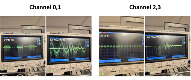
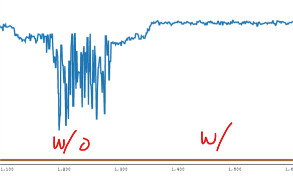
However, when I switch to measuring a different capacitor (with a different value), the measurements appear to be completely inaccurate or inconsistent. It seems that the configuration does not automatically adjust or re-calibrate based on the new capacitor value, and I am not sure why the system behaves this way. (ex, LC configuration adjusted for 200nF for four channels and if we connect 100pF the measurement goes to 1F?)
Could you please advise on how to correctly reconfigure or stabilize the LC tank settings when changing to a different capacitor? Is there a recommended procedure to ensure accurate readings after such changes?
Any guidance or documentation you could provide would be greatly appreciated.
Thank you very much for your time and support!
Warm regards,
Ju-Yong Lee