This thread has been locked.

If you have a related question, please click the "Ask a related question" button in the top right corner. The newly created question will be automatically linked to this question.

AWR2243: Available chirp transfer time over CSI

Part Number: AWR2243

Tool/software:

I am seeking clarification on the time available for transferring chirps over CSI

From SWRA555A - AWR1xxx and AWR22xx Data Path

The AWR2243 has a ping-pong buffer for storing chirps, allowing a chirp to be read into the ping buffer while the pong buffer is transferred over CSI/LVDS.

The key DFE events that trigger the state machine are the “Frame Start” and “Chirp(s) Available” events.
The “Chirp(s) Available” event is generated during every ping-pong switch of the ADC buffer. On every
“Chirp(s) Available” event, the CBUFF kicks the eDMA configured eDMA channel for the transfer and the
flow control mechanism ensures the complete transfer of the data over the HSI interface. - Section 4.1.1 State Machine
 
So whenever the ADC sampling for a chirp ends, a Chirp(s) Available event is generated and the buffer switches from being read into, to being transferred out.

So from this, it seems like I have until the subsequent Chirp(s) Available event to transfer my data over CSI. Put another way, the upper limit on CSI transfer time is the time between one chirp ADC sample finishing, and the successive chirp ADC sample finishing.

From SWRA553A - Programming Chirp Parameters in TI Radar Devices

However, in SWRA553A, there is a short note that the time available for data transfer is ramp end time + idle time.

From the provided timing diagram, and given AWR2243 has ping-pong buffers, I understand this to mean the available chirp transfer time is the idle time of the successive chirp + the ramp end time of the successive chirp
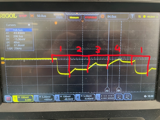
Testing

I have tested the available CSI transfer time, and I have found that if I follow the assumption but forward in Programming Chirp Parameters in TI Radar Devices, there is insufficient time to read out the data over CSI, and the AWR2243 generates MSSCPUFAULTs.

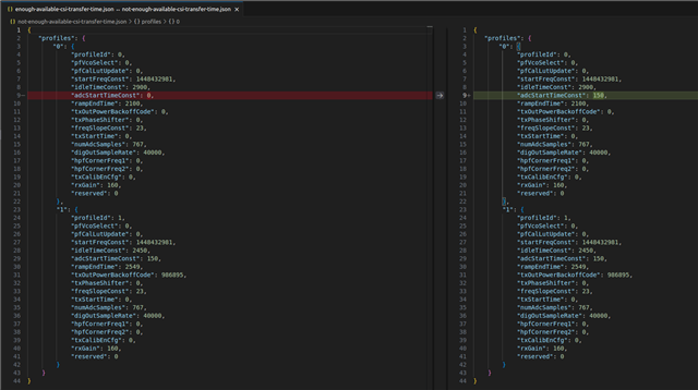
However, if I increase the time between ADC sampling ends (Chirp Available events), the CSI transfer seems to work without issues. Note I am not changing the chirp cycle time (idle time before chirp + ramp end time), I am only moving the ADC sampling within the ramp end time to change this timing.

So, as I understand it, the time available for data transfer calculation in SWRA553A should not be relied on, and it more just to demonstrate the need to configure other chirp parameters not accounted for in the ramp timing calculator. It is not meant to be used as a precise reference for available chirp transfer time, except in a very simplified case where ADC timing precisely aligns with the ramp end time

The actual available chirp transfer time is the time between Chirp(s) Available events, which can be increased by increasing idle time, among other chirp parameters

Questions

My questions are

  1. Am I right in assuming that the available chirp transfer time is the time between successive Chirp(s) Available events, which, if configured for only one chirp per buffer, will be equal to the time between successive ADC samples ending? So I can control the available transfer time by changing the timing of ADC sampling?
  2. If this is true, then I should be able to increase the available chirp transfer time by increasing the number of chirps to be stored in each of the ping-pong buffers (as per SWRA555A - 2.1.4 Ping Pong Switch Select). Is there any guide to how I can change DSS_REG:ADCBUFCFG4 to allow two chirps to be read into each ping-pong buffer? It doesnt seem to be available through the mmwavelink ICD so I assume the change must be made directly to firmware?
  3. could you please confirm that the chirp cycle time is composed of idle time first and then ramp end time (as seems to be indicated in Figure 7)?

Thanks very much!

  • Hello Rex,

    1) Yes the time between the chirp available events is when you can stream out the data.

    2) No you can increase this by providing more chirp idle time and also for the duration of the chirp as well

    3) no its ramp end time then chirp idle time.

    Regards,
    Saswat Kumar

  • Hi Saswat,

    For our application these questions are quite critical so I have a few follow up points

    1) As I understand it, increasing chirp idle time and chirp duration only increases the available transfer time indirectly because it increases the time between chirp available events at the end of ADC sampling. You can increase the available chirp transfer time by only changing ADC_START_TIME_CONST. I have tested this and I have included the basic profile configurations I used (see `enough/not-enough-available-csi-transfer.json`). The only difference between the two is that I increase ADC_START_TIME_CONST from 0->150 for the first chirp, reducing the time between chirp(s) available events, which is enough to cause an issue with the CSI transfer time.

    {
       "profiles": {
           "0": {
                "profileId": 0,
                "pfVcoSelect": 0,
                "pfCalLutUpdate": 0,
                "startFreqConst": 1448432981,
                "idleTimeConst": 2900,
                "adcStartTimeConst": 0,
                "rampEndTime": 2100,
                "txOutPowerBackoffCode": 0,
                "txPhaseShifter": 0,
                "freqSlopeConst": 23,
                "txStartTime": 0,
                "numAdcSamples": 767,
                "digOutSampleRate": 40000,
                "hpfCornerFreq1": 0,
                "hpfCornerFreq2": 0,
                "txCalibEnCfg": 0,
                "rxGain": 160,
                "reserved": 0
            },
            "1": {
                "profileId": 1,
                "pfVcoSelect": 0,
                "pfCalLutUpdate": 0,
                "startFreqConst": 1448432981,
                "idleTimeConst": 2450,
                "adcStartTimeConst": 150,
                "rampEndTime": 2549,
                "txOutPowerBackoffCode": 986895,
                "txPhaseShifter": 0,
                "freqSlopeConst": 23,
                "txStartTime": 0,
                "numAdcSamples": 767,
                "digOutSampleRate": 40000,
                "hpfCornerFreq1": 0,
                "hpfCornerFreq2": 0,
                "txCalibEnCfg": 0,
                "rxGain": 160,
                "reserved": 0
            }
        }
    }

    So if I increase the time between chirp available events (which your suggestion to increase idle time and chirp duration indirectly does), I can increase available CSI transfer time. Given that, I am unclear as to why increasing ADCBUFNUMCHRPPING/ADCBUFNUMCHRPPONG in DSS_REG:ADCBUFCFG4 wouldnt increase available CSI transfer time, given this would directly increase the time between chirp available events?

    2) I have seen ramp end time then chirp idle time quoted in many places, but it seems to be the exact opposite of what is shown in Figure 7, where chirp cycle time is made up of chirp idle time and then ramp end time! 

    I have actually tested this as well, and the basic configuration is 

    {
       "profiles": {
            "0": {
                "profileId": 0,
                "pfVcoSelect": 0,
                "pfCalLutUpdate": 0,
                "startFreqConst": 1448432981,
                "idleTimeConst": 1000,
                "adcStartTimeConst": 0,
                "rampEndTime": 4000,
                "txOutPowerBackoffCode": 0,
                "txPhaseShifter": 0,
                "freqSlopeConst": 23,
                "txStartTime": 0,
                "numAdcSamples": 767,
                "digOutSampleRate": 40000,
                "hpfCornerFreq1": 0,
                "hpfCornerFreq2": 0,
                "txCalibEnCfg": 0,
                "rxGain": 160,
                "reserved": 0
            },
            "1": {
                "profileId": 1,
                "pfVcoSelect": 0,
                "pfCalLutUpdate": 0,
                "startFreqConst": 1448880373,
                "idleTimeConst": 2000,
                "adcStartTimeConst": 0,
                "rampEndTime": 4000,
                "txOutPowerBackoffCode": 197379,
                "txPhaseShifter": 0,
                "freqSlopeConst": -23,
                "txStartTime": 0,
                "numAdcSamples": 767,
                "digOutSampleRate": 40000,
                "hpfCornerFreq1": 0,
                "hpfCornerFreq2": 0,
                "txCalibEnCfg": 0,
                "rxGain": 160,
                "reserved": 0
            },
            "2": {
                "profileId": 2,
                "pfVcoSelect": 0,
                "pfCalLutUpdate": 0,
                "startFreqConst": 1448432981,
                "idleTimeConst": 3000,
                "adcStartTimeConst": 150,
                "rampEndTime": 4000,
                "txOutPowerBackoffCode": 394758,
                "txPhaseShifter": 0,
                "freqSlopeConst": 23,
                "txStartTime": 0,
                "numAdcSamples": 767,
                "digOutSampleRate": 40000,
                "hpfCornerFreq1": 0,
                "hpfCornerFreq2": 0,
                "txCalibEnCfg": 0,
                "rxGain": 160,
                "reserved": 0
            },
            "3": {
                "profileId": 3,
                "pfVcoSelect": 0,
                "pfCalLutUpdate": 0,
                "startFreqConst": 1448880373,
                "idleTimeConst": 4000,
                "adcStartTimeConst": 150,
                "rampEndTime": 4000,
                "txOutPowerBackoffCode": 592137,
                "txPhaseShifter": 0,
                "freqSlopeConst": -23,
                "txStartTime": 0,
                "numAdcSamples": 767,
                "digOutSampleRate": 40000,
                "hpfCornerFreq1": 0,
                "hpfCornerFreq2": 0,
                "txCalibEnCfg": 0,
                "rxGain": 160,
                "reserved": 0
            }
        },
        "chirps": {
            "0": {
                "chirpStartIdx": 0,
                "chirpEndIdx": 0,
                "profileId": 0,
                "reserved": 0,
                "startFreqVar": 0,
                "freqSlopeVar": 0,
                "idleTimeVar": 0,
                "adcStartTimeVar": 0,
                "txEnable": 4
            },
            "1": {
                "chirpStartIdx": 1,
                "chirpEndIdx": 1,
                "profileId": 1,
                "reserved": 0,
                "startFreqVar": 0,
                "freqSlopeVar": 0,
                "idleTimeVar": 0,
                "adcStartTimeVar": 0,
                "txEnable": 4
            },
            "2": {
                "chirpStartIdx": 2,
                "chirpEndIdx": 2,
                "profileId": 2,
                "reserved": 0,
                "startFreqVar": 0,
                "freqSlopeVar": 0,
                "idleTimeVar": 0,
                "adcStartTimeVar": 0,
                "txEnable": 4
            },
            "3": {
                "chirpStartIdx": 3,
                "chirpEndIdx": 3,
                "profileId": 3,
                "reserved": 0,
                "startFreqVar": 0,
                "freqSlopeVar": 0,
                "idleTimeVar": 0,
                "adcStartTimeVar": 0,
                "txEnable": 4
            }
        }
    }


    Basically, I have four profiles, each applied to a chirp, and these four chirps repeat. The first chirp has an idle time of 1000, seocnd 2000, then 3000, then 4000. To help visualise I have also changed the transmit power so its easy to distinguish each chirp. I have attached an image of measurements made with a power detector and scope, and labelled chirp 1-4

    for example:

    • Chirp 4 (the lowest power chirp) has a 4000 ns idle time, which clearly shows up at the start of the chirp, followed by the ramp.

    • Then Chirp 1 (the highest power chirp), with 1000 ns idle time, shows a short gap before ramping up.

    I have also measured the idle time for the other chirps and I can confirm that the order is programmed idle time and THEN ramp time.

    If it really is ramp end time and then chirp idle time, what am I seeing in these measurements?

    3) If it is in fact idle time and then ramp end time, does that mean the actual available transfer time for chirp x is the idle time for chirp x+1 plus the adc sample duration for chirp x+1

    Thanks,

    Rex

  • Hello Rex,

    1) You cannot write to that register. There is no means to write to it, since it is a front-end streaming device. This is why I mentioned to increase the chirp idle.

    2) So sorry for the mistype in that answer: you are right it is idle time + ramp time after that. I also cross checked for confirmation on this particular query.

    Regards,
    Saswat Kumar

  • Thanks Saswat, much appreciated