This thread has been locked.

If you have a related question, please click the "Ask a related question" button in the top right corner. The newly created question will be automatically linked to this question.

TUSS4470: OUT A and B no output wave

Part Number: TUSS4470

Tool/software:

TUSS4470_Write_Register(&hspi1, GPIOA, GPIO_PIN_4, DEV_CTRL_3,0x00);

DEV_CTRL_3 ,0

MODE0

TUSS4470_Write_Register(&hspi1, GPIOA, GPIO_PIN_4, BURST_PULSE,0x88);

BURST_PULSE : HALF MODE =1       8 PULSE

TUSS4470_Write_Register(&hspi1, GPIOA, GPIO_PIN_4, TOF_CONFIG,0x01);

TOF 1

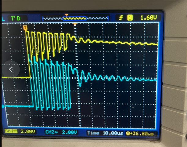
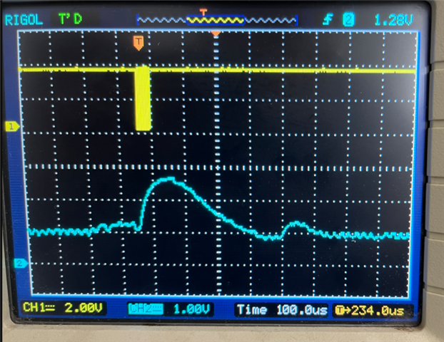
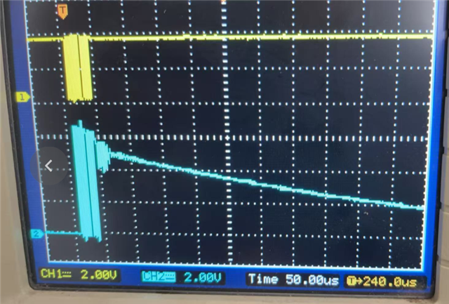
then Send pulses,no output

and another question:

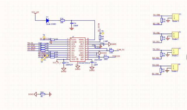
That's what my schematic diagram is same. I need to configure it with a center frequency of 200Khz, bandpass, and the maximum receive gain, and then determine the corresponding registers

The following is the current configuration:

BPF_CONFIG_1 = 0X9E BPF_CONFIG_2 = 0x08 DEV_CTRL_1 = 0x00 DEV_CTRL_2 = 0x02

VDRV_CTRL = 0x18 ECHO_INT_CONFIG = 0x1A

ZC_CONFIG = 0x00

  • Hi Hui,

    Sorry for the delayed response.  

    Can you confirm that you are succesfully writing and reading back registers?  Can you read back the same value that you write to a register?  

  • The read Device ID is 0xB9

    BPF_CONFIG_1 read and write consistent

    BPF_CONFIG_2 read-write inconsistency: Fixed 0x00

    DEV_CTRL_1 read/write inconsistency: Fix 0x0E

    DEV_CTRL_2 reads and writes consistently

    DEV_CTRL_3 read/write inconsistency: Fix 0x00

    VDRV_CTRL reads and writes consistently

    ECHO_INT_CONFIG read/write inconsistency: Fix 0x07

    ZC_CONFIG read/write inconsistency: Fix 0x14

    BURST_PULSE reads and writes consistently

    TOF_CONFIG read/write inconsistency: Fix 0x00

  • Hui,

    Please provide logic analyzer shots of the communication as well.  This can help to determine if there is a communication or timing issue.  Thanks!

  • The reading and writing have been consistent and there is already output. The blue waveform is the ultrasonic wave transmitting end, and the yellow waveform is the ultrasonic wave receiving end. The two are almost simultaneous. Is this normal? What kind of waveform should I normally receive?


  • Yes, this is expected.  When the pulses are transmitted, the receiver will also pick this up.  If an echo is received, it is expected that you would see a spike later in time that corresponds to the time of flight of the echo signal.  See the image below from the EVM and GUI plot.  The signal seen at ~11ms is the echo.  

  • I have two questions about this at present. 1. After the ultrasonic wave is sent earlier, the aftershock of the ultrasonic wave is very large. How can we directly make the sent waveform fall directly to the bottom with the aftershock as small as possible? If it is too long, the waveform of the subsequent echo may overlap with the afterwave, making it difficult to distinguish. It's the long slope as shown in Figure 2

    2. For the subsequent echo part, how can the gain be set to be further amplified as much as possible to be as consistent in size as the previous part

  • Hui,

    Yes, in a monostatic topology there is ringdown of the transducer that is observed on the transducer.  A dampening resistor can be added to reduce the ringdown, but it will not eliminate it.  To eliminate, you would need a bistatic topology using seperate transmit and receive transducers.  See section 2.4 of the app note below.

    https://www.ti.com/lit/an/slaa907d/slaa907d.pdf 

    You can add gain using the internal amplifiers.  See section 7.3.3 of the datasheet below.

    https://www.ti.com/lit/an/slaa907d/slaa907d.pdf  

    There is also good information in the app note below regarding usage of the device.

    https://www.ti.com/lit/an/slda058/slda058.pdf