This thread has been locked.

If you have a related question, please click the "Ask a related question" button in the top right corner. The newly created question will be automatically linked to this question.

LDC1312: Inductor coil design & query

Part Number: LDC1312
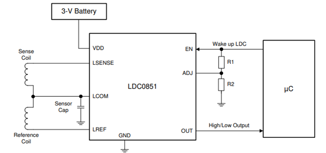
Other Parts Discussed in Thread: LDC1612, LDC0851, LDC0851EVM

Tool/software:

Dear Sir,
Good Day!
Project: LPG Monitoring Unit

We are working on a project that requires detection of the welded metal part on an LPG gas cylinder — specifically the portion used to support the RIM for holding.
For this purpose, we are planning to use the LDC1312 Inductance-to-Digital Converter IC. The required sensing distance is approximately 20 mm.
Could you please guide us on the feasibility of using the LDC1312 for this application, and share any relevant application notes or design considerations?
Looking forward to your support.
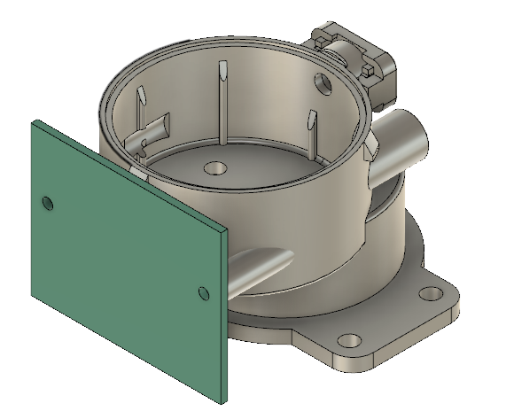
Please refer below image where PCB will fit & inductance (circular track) will generated on front side of PCB. Enclosure material is PC. In enclosure DC motor will be fit which is back side of PCB. We plan to make inductance on front side of PCB. Sensing distance is 20mm. We have below queries.
1. Does the motor will make impact on inductance ?
2. Does it sense MS from 20mm with 20mm Diameter of sensing inductance ?
3. Can we make inductance on single side (front side of PCB) ?
4. Please share India (Pune) office contact details. Email ID & telephone number.
Best regards,
Dattatray Salunke
Maestrotek Innovations Pvt. Ltd.
A-1408, 14th Floor, Gokhale Business Bay,
Paschimanagri, Kothrud, Opposite City Pride Theatre,
Pune – 411038, Maharashtra, India
Mobile: +91-8087590560
www.maestrotek.co
  • Hello Dattatray,
    Please see my comments below.
    1. Does the motor will make impact on inductance ?  
    The motor could have some impact on the inductance depending on the spacing from the coil.  This would need to be tested in your system.  Shielding of the coil may be able to help mitigate some of the effects.  See the app note below.
    2. Does it sense MS from 20mm with 20mm Diameter of sensing inductance ?
    Typically, the achievable range is about half the diameter of the coil.  To reach 20mm, you would need a coil diameter of around 40mm.  See the app note below regarding sensor design.
    3. Can we make inductance on single side (front side of PCB) ?
    Yes, the coil can be implemented on a single layer PCB.  
    4. Please share India (Pune) office contact details. Email ID & telephone number.

  • We have a size constraint — our PCB size is 30x30 mm.
    Could you please suggest how we can detect MS under this constraint?

    Also, kindly share the contact details (email ID and telephone number) of your India (Pune) office.

    www.ti.com/.../contact-us.html The link provided by you is not useful. In this link, no email ID & telephone mentioned, 

  • Dattatray,

    I would recommend using the largest size coil possible, 30mm diameter if you use a circular coil.  I also recommend using the LDC1612 device to obtain the largest possible range.  The LDC161x is a higher resolution device and is able to detect from a larger distance, up to 1.5x the coil diameter.  This device is also pin to pin compatible with the LDC1312, so you could test with both devices, but LDC1612 should offer the greatest range.

    In regards to contact information, I do not have any direct contact for you in India.  This e2e forum will be the best place for support if you don't have an assigned local engineer.

  • Our PCB size is changed to 26x33mm. We want to use LDC0851 to sense the MS metal. Sensing distance is 10mm. We want to use double sided PCB. We can make coil of 25mm diameter. Please refer below application circuit


    How to connect Sense coil end point & Ref. coil start point to LCOM ?

    How we can make the coil for double sided PCB ?

    If you have PCB layout in fusion, please share.

    Please guide.

    Regards,

    Dattatray

  • Dattatray,

    If you have 25mm diameter available, I would recommend using a stacked coil design for LDC0851.  See the app note below regarding this type of design.  I don't believe we have any PCB examples with a 2 layer PCB.  I would suggest looking at the LDC0851EVM as a reference which uses 4 layers.  

    https://www.ti.com/lit/an/snoa982/snoa982.pdf 

    https://www.ti.com/tool/LDC0851EVM