This thread has been locked.

If you have a related question, please click the "Ask a related question" button in the top right corner. The newly created question will be automatically linked to this question.

TMP006 ambient light sensitivity

Other Parts Discussed in Thread: TMP006

    I am developing a non contact flowmeter device using 630nm illumination of a target from an LED through

an optical fibre. We use approximately 250mw optical power to heat the target, and the eventual system will

use modulated LED intensity to induce a constant temperature increase on the target. The optical power

required will correlate with flow.

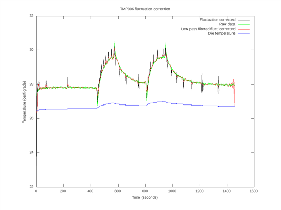
   During basic testing with a TMP006 evaluation board we have noticed spikes on the output each time the

illumination is turned on/off. We suspect this is due to photovoltaic effects from the illumination light reflecting

between the IC and the PCB and striking the "bottom" side of the IC.  This only seems to occur when the

illumination intensity is rapidly changed - e.g. a 0 to100mw slew over 10 seconds or similar with our setup

(approximately 10% of input light is reflecting and hitting the sensor).

   Could anyone advise on the possible causes of this effect, and if the photovoltaic hypothesis is credible.

What steps could we take to mitigate the spiking apart from reducing the optical power slew rate.

  • I may have some insight into the issue - after reading the forums I came across the fluctuation correction feature, which i wasn't using.

    I've implemented the correction in matlab and reanilised the data, and it looks like the sudden heating/cooling of the sensor die when the light source is turned on/off may be to blame. Unfortunately the die temperature noise is much less than one lsb on the adc, which means the algorithm is working very poorly and producing 1lsb ambient change induced spikes everywhere. I'm not sure if this is due to my sensor having particularly low noise on the ambient channel?

    I'm also guessing the correction technique is taylored to pcb temperature induced fluctuations with the recommended pcb layout, which might also explain my poor results.

     Unless anyone can suggest some better ideas im going to try reducing heating by fixing aluminised mylar film with a 1mm square hole over the sensor using 3M spray adhesive. EDIT: Trying a T_slope estimator that interpolates between each die temperature change gives better results, but there are still large artefacts.

  • I've now rerun the experiment with mylar over the sensor front and custom fluctuation correction using die temperature interpolation. Results are a lot nicer,

    there is still some heating of the sensor, it seems to now be only by convection through the air. A custom pcb with heatsinking of the tmp006 to a large

    copper ground plane on the back side should allow the sensor to come into better equilibrium with the room air.

    One interesting effect is the LED optical efficiency decreasing as its temperature increases. This can be seen as a higher peak just after the LED is turned on at 300 seconds.

    A better LED heatsink would help!