This thread has been locked.

If you have a related question, please click the "Ask a related question" button in the top right corner. The newly created question will be automatically linked to this question.

AWR2944: Do TI have a more detail document about LVDS and AURORA

Part Number: AWR2944

Tool/software:

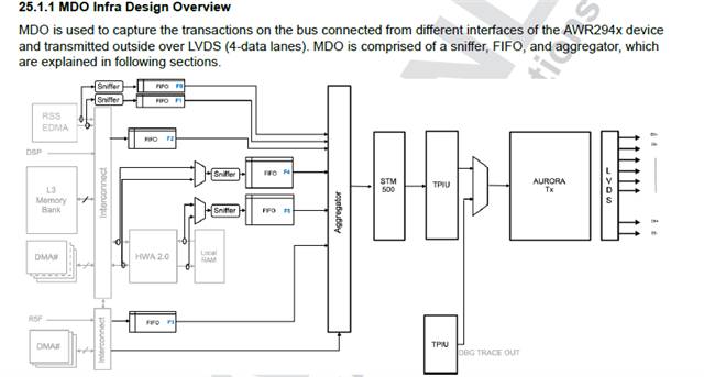
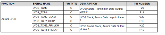
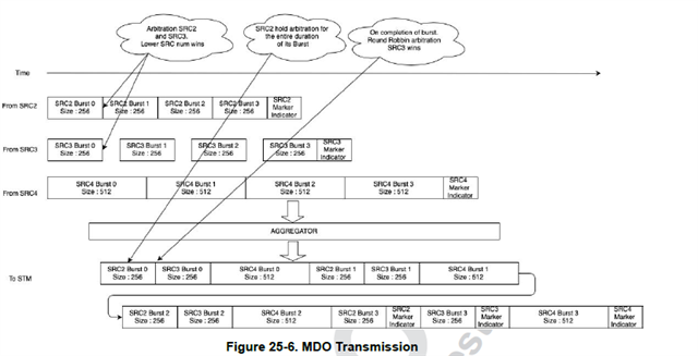
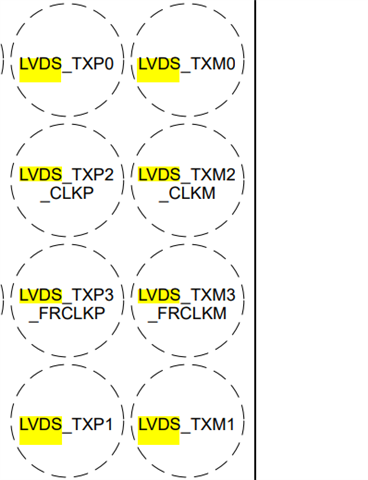
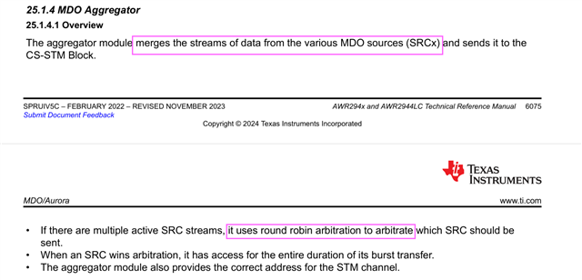
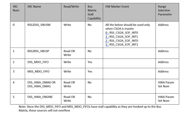
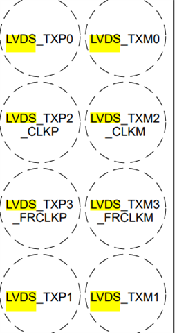
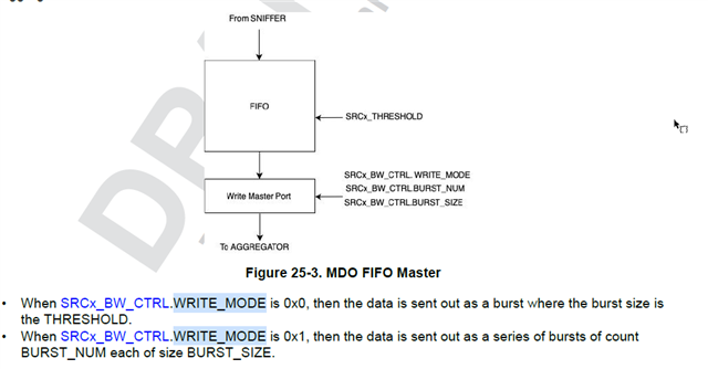
the aurora part in the user manual don't have enough information about the transmit mode ,  the max size of DMA and each FIFO size , and how the aggregator work , the max size of aurora transmit , and the architecture of the 4 lane LVDS , do TI have more detail information about these parts?

  • and TI document have a special number like sprugh7(represent DSP instruction set), how to find the corresponding document or the specific number

  • Hello xing,

    There is no user manual, just whatever is present in the TRM.
    Can you tell me what exact information are you looking for?

    Regards,
    Saswat Kumar

  • Hello Kumar, according to the TPM 2944 have 4 LVDS data lanes, but the data sheet show only one pair of data lane and two pair of clock lane, how to understand the 4 data lanes output? and which FIFO is output to which LVDS lane?


    and TPM said 2944 support 4 LVDS output or 2 aurora output , which pins are used for Aurora output , the LVDS_TXM0/P0 and LVDS_EXM2_CLKM/LVDS_TXP2_CLKP?

    and what is the SRCX? does it stand for the FIFO buffer?, do we have a mapping about each SRC stand for which FIFO?
    If a FIFO threshold is reached, and the data is transmit to aggregator, when does the aggregator trigger a transmit ?

    Regards

  • Hello Xing,

    1) It has 4 Aurora lanes, not the LVDS lanes. For the LVDS lanes you require clock signals as well due to which you it is mentioned as clock.
    Aurora runs on the 4 lanes itself and it has 4 differential lanes for the same:

    There is no FIFO to lane mapping, as mentioned in the TRM, the FIFO value is inputted into the aggregator which works in the following way:

    You can find the SRC mapping here:


    The above is the latest one which will be fixed in next TRM update.

    Regards,
    Saswat Kumar

  • Hello Kumar, 

    Thanks for the explanation ,  i am still confused about the "Aurora runs on the 4 lanes itself and it has 4 differential lanes for the same" 

     does 4 aurora lanes means these four pairs of physical pin can be individually configured as Aurora signal outputs?

  • Hello xing,

    So these are differential lanes so a combination of 2 makes 1 lane. You can see 8 pins so there are totally 4 lanes.

    Regards,
    Saswat Kumar

  • and if i want to config the transmit size, if the write_mode is 0 , the fifo reach the threshold which set by SRC0_THRESHOLD Register then transmit data to aggregator ,right.? 

    Then if the data size reach the AURORA_TX_UDP_SIZE register value , then pack the data to UDP packet format , and trigger a output  to the physical port , am i right ? 

    and the UDP header data, what is this header? is this a standard format?

  • Hello Xing,

    Yes Fifo reached the threshold set by the SRCx_THRESHOLD it will send out the data to aggregator

    And once you have enough data for the packet it will send the data over the aurora

    The header is a standard format in aurora and it is up to you whether or not you want it and can perform similar configuration.

    Regards,
    Saswat Kumar